Encapsulting Protocols

  1. Secure Shell (SSH )
  2. Encapsulating protocols at Network Layer
    1. IP in IP
    2. Multiprotocol Label Switching (MPLS)
    3. ESP (Encapsulating Security Payload)
  3. Encapsulating protocols at Transport Layer
    1. TLS and Datagram Transport Layer Security (DTLS)
    2. Generic Routing Encapsulation (GRE)
    3. QUIC
    4. TCP encapsulation
  4. Subtle points of using encapsulation
    1. Path MTU and fragmentation
    2. Migration of inner payload from one to another protocol
    3. Prioritization and congestion post encapsulation
      1. Misordering
      2. Loss of ECN signal
    4. Classification and tagging
    5. State Synchronization in Multipath
      1. Applying policies
      2. Anti-replay window synchronization
  5. Protocol Design for an encapsulating protocol
    1. Traffic Fow confidentiality ( TFC)
    2. Segmentation of information into header and trailer
    3. Dynamically adjustable anti-replay window sizes
    4. Security constraints

Encapsulation is the process of encasing the payload sent by an endpoint into another protocol’s payload, attaching its own header and trailer. This is applied to all data being processed by the network stack layers. For example, an HTTP ( L7 application layer protocol) is encapsulated under a TCP header (L4 layer protocol ) and further in an IP header ( L3 protocol) and so on until it is down to the physical layer.

Network stack encapsulation accross layers

This article doesn’t deal with encapsulation across the general network stack but rather focuses on encapsulating protocols that try to mask the identity of the original payload from network middleboxes to provide anonymity or virtualized networking.

Core parts of a secure communication framework relying on encapsulation are

  • Encapsulation and decapsulation ( encap and decap) libraries on the receiver and sender as well as a means to exchange the metadata enabling encap-decap.
  •  The payload, which is an original packet, optionally including upper-layer protocols, can be encrypted or plain.
  •  Algorithms and tools to order packets arriving out of order and duplicated
  •  Provide confidentiality as well as detection against malicious activities like MITM attacks or other kinds of passive attacks such as eavesdropping and replaying.

Sequnece Numbers are monotonically increasing numbers that show the ordering of the packets in a stream. They do not necessarily start from 0. Most sequence numbers have a wrapping feature, especially useful for long-lived connections. At the far end of the valid sequence number range, the sequence numbers can go down to the beginning after maxing out. First used in TCP, sequence numbers have become popular in the most reliable communication protocols. Primarily meant for reordering the incoming packets in traffic in the correct order, these numbers can be used for other purposes as well.

  • Sequence numbers in the headers, such as ESP, help maintain the anti-replay window, which prevents attacks from replaying previously captured data. Any packet coming from a sequence outside the window is either a retransmission or a replay attack and, hence, can be more scrutinized.
  • In some cases of ESP, even extended sequence numbers are used, which can be controlled by the cryptographic algorithm making it a security enhancement.

Security Association between the endpoints of an encapsulated path. Security Association is a critical aspect of securing a communication path with a crypto algorithm, integration, keys, etc, and is used especially in the case of IPsec.

Sharing Keys : Maual keying , static configuration based keying and most recommended, Key exchange protocols such as IKE ( Internet Key exchange) can be used to share secret keys.

Unique identification : The onus of unique identification of the multiple paths/streams and the order of packets in the individual paths/streams lies with the creator of the header that would be attached to the encapsulated payload. Such a unique identifier or set of attributes should be able to distinguish multiple coexisting tunnels. Some example of unique Id/ identifiers in multioplexed usecase in case of non tunneling usecases are

  • HTTP/2 uses stream ID for multiplexed flows within a single connection
  • SIP uses Session ID

Simmilarly example of unique Id/ identifier in case of tunneling are

  • GRE uses the key field to make distuiction between individual flows
  • MPLS uses labels to identify diferent strems associated with different classes.
  • ESP uses SPI to attach the cryptographic SA keys to each packet for processing.
  • L2TP ( Layer 2 Tunneling protocol) also uses tunnel ID to identify coexisting tunnels.
  • SPI used in IPSec ESP protocol is a 32-bit identifier that bounds a security association to a packet. This is used to demultiplex inbound traffic at the receiver’s end.
  • QUIC uses connection ID

Others can rely on sequence numbers as counters or even destination address mappings to identify the path/stream. However, these approaches have many limitations. Most protocols would try to attach a new custom field.

More description on some encapsulating protocols

Secure Shell (SSH )

While ssh is not generally thought of as a tnunneling protocol , it does create a communicaion link for remote access and file transfer to happen securly. Hence forming the crux of what is considered a VPN functionality.

Encapsulating protocols at Network Layer

IP in IP

As IPV4 in IPv4 , IPV4 in IPv6 , IPv6 in IPv4 , and IPv6 in IPv6, are most commonly used for network virtualization ( VPN) and other kinds of Network as service such as Secure Access Service Edge (SASE).

IPv6 over IPv4

Multiprotocol Label Switching (MPLS)

MPLS can transport IP packets ( IPv4 and IPv6) over IPv4 backbone.Orignally design for forwarding and routing, instead of trraditional IP based routing MPLS uses packet labels to make next hop routing decisions. This enables creation of paths based on QoS. In contrast to ESP which is applied at layer 3, MPLs operated at layer 2.5( between layer 2 and 3).

Original packet and modified packet with MPLS header format

ESP (Encapsulating Security Payload)

ESP, part of the IPSec suite, enables confidentiality, integrity, and authenticity for IP packets it encapsulates. ESP header contains

  • SPI ( Security Parameter Index) to links SA ( security association) with an endpoint
  •  Sequence number, which is a counter to prevent a replay attack
  •  payload type can be encrypted or plain
  • followed by the Next header, which specifies the type of original IP packet in the payload.

ESP can operate in transport mode (protecting the payload of an IP packet) or tunnel mode (protecting the entire IP packet).

Generic
IP packet
Transport ModeTunnel Mode

Authetication Header
ESP

Without considering encryption or authentication overhead, the basic ESP header is 8 bytes in size. The ESP H( header) is realitively smaller in transport mode than in tunnel mode.

IPV4
IPv6
Transport ModeTunnel Model
IPv4
IPv6
IPv4 and IPv6 in transport and tunnel modes for ESP.

Encapsulating protocols at Transport Layer

TLS and Datagram Transport Layer Security (DTLS)

While TLS is designed for TCP, DTLS securily encapsulates datagrams over UDP. In contrast to ESP which encapsulates traffic for VPN usecases , DTLS is mostly used to encapsulate real time data traffic suhc as in WebRTC, gaming.

Generic Routing Encapsulation (GRE)

Another layer 4 tunneling protocol is GRE. It is protocol agnostic to layer 3 payloads as in it can tunnel any layer 3 protocol from IPv6, IPv4 to other raw formats. The “Protocol Type” fiels in GRE header specifies the protocol type of the encapsulated packet. GRE has a minimal header structure with no out of box security such as encrytion.

GRE tunnel forming a site to site VPN

QUIC

QUIC encapsulates higher-layer protocols, such as HTTP/3, within its own transport layer over UDP. Besides efficient multiplexing, encryption , QUIC also excels at migration and quick handshakes.

In contrarst to ESP , while ESP is part of IPSec suite of protocol aimed at lower underlay layer tunnleing, QUIC is aimed at application data encapsulation like web traffic and leverages UDP itself , appendning its own header with control information.

Note that MASQUE is another enacpsulation protocol build over QUIC. As these are still nascent and eveolving I will update this section as more specificatiosn are standardised.

TCP encapsulation

Many network middleboxes that filter traffic on public hotspots block all UDP traffic. As a result, UDP traffic, such as media streams for VoIP calls or even IKEv2 UDP packets, gets blocked. But middleboxes are likely to allow TCP connections through because they appear to be web traffic

  • (+) provides NAT support
  •  (+) Avoids UDP fragmentation
  •  (-) overhead of TCP or TLS

While designing a TCP-based encapsulation, it is recommended that Initiators should only use TCP encapsulation when traffic over UDP is blocked. TCP can leverage the streams over a single TCP connection to send data across. This way, any firewall or NAT mappings allocated for the TCP connection apply to all of the traffic associated with the encapsulated packet. This prevents large number of roundtrips.

Subtle points of using encapsulation

In addition to encapsulation overhead and reachability, the following are concerns that occur in encapsulating the data and traversing through a complex network.

Path MTU and fragmentation

Path MTU discovery messages such as ICMP can be blanket blocked by firewalls, which prevents proper MTU from being set for the encapsulated and overall packet. Subsequently, the MTU of the endcap packet may exceed the path MTU, leading to fragmentation, leading to

  • latency in transmission
  • undecipherable or unroutable packets by middleboxes / VPN hubs
  • Fragmented packets received may be unprocessable or not be able to be disassembled properly, which is countered by packet loss, leading to retransmission and further congestion.

Migration of inner payload from one to another protocol

For IPv4 encapsulating other IPs in a dual-stack implementation, sometimes the destination can decide to upgrade, such as from IPv4 to IPv6. The upgrade involves periods of simultaneously using IPv4 and IPv6 and then a gradual transition towards IPv6. The key differenece between the IPv4 and IPv6

  • header size which is 20 bytes and 40 bytes for IPv4 and IPv6 repectively.
  • only IPv4 supports fragmenetation
  • IPv4 has nique adddress space thus NAT is not needed as much as with limited addressing of IPv4

With migration ineffect on a dual stack impact on as the overlay depends on the underlay protocols ability to carry its traffic. For example in IPv6 over IPv4, as IPV4 underlays are well adopted in network infrastructure, original payload packets with ipv6 header use the ipv4 as encapsulating packet IP to carry accross the tunnel. BGP and OSPF are common routing and forwrading protocols for a IPv4 underlay network.

IPv4IPv6
OverlayIPv4 over IPv6
IPv4 over IPv4 ( GRE)
IPv6 over IPv4 ( 6in4)
IPv6 over IPv6

Prioritization and congestion post encapsulation

Many network middleboxes ( routers, cloud firewalls, gateways, and so on ) implement traffic filtering, shaping, or queue management based on prioritization( AQM at ISPs). Due to the masked nature of encapsulated packets, there is a high chance of the middleboxes not being able to ascertain their identity and, thus, making it deprioritized.

Misordering

To still keep the endpoints connected, the packets thus need to be put in the correct order with manageable latency at the receiving endpoint. This is especially critical for encapsulating packets for low-latency applications. For example, for video codec, a keyframe encapsulated packets arriving late could affect all subsequent packets to wait in the receiver buffer. This cascaded into a downward spiral of sending selective acknowledgments, retransmission, and discarding arrived packets, which can further intensified the problem.

Loss of ECN signal

Some systems overcome this by copying the ECN header from the inner header of the original packet to the outside headers. However, this needs to be a mutable field as the packet traverses through the many nodes of a large network. This is not protected by the integrator algorithms, and thus, for the risk of being misused, once a feature, this is now dropped by the updated specifications of many encapsulating protocols, such as IPsec.

Classification and tagging

Classification and tagging of traffic within a stream of encapsulated packets is also a challenge. The payload of the encapsulated packets could contain mixed content that cannot be tagged to any specific class, which can be used to prioritize real-time or critical traffic. For example, DSCP tag propagation from inner to outer packets can help in this direction but runs the risk of traffic profiling by middleboxes.

State Synchronization in Multipath

Scaling to involve multiple streams in a session using encapsulation poses challenges. This problem is further amplified in the case of multi-sender and multi-receiver scenarios.

Applying policies

For a stateful, contextual, and intelligent decision-making process, a sender needs to leverage the multiple available paths. It needs to discover alternate reachable paths and collect and sync network metrics to use the resources matching the needs of time sensitivity, cost, etc.

Anti-replay window synchronization

Difficulty in synchronizing anti-replay windows when multiple paths are involved impacts load-sharing encapsulated traffic. Additional issues may involve multicore or distributed operations.
A short-term solution to Sync issues is to have a very large Anti-replay window. Patching this with a short-term change of making the anti-replay window too big increases the possibility of packets being too far in sequence, which further leads to unpredictability in ordering. In high throughput scenarios, it may even be difficult for the CPU to keep the state in cache for an immensely large window size, thus causing undue latency penalties.

Protocol Design for an encapsulating protocol

Traffic Fow confidentiality ( TFC)

Primarily, an encapsulating protocol needs to make the traffic from outside visibility, which can be done by rewriting the source destination information as well as encrypting and/or padding the payload so as to not make it intelligible to middleboxes. Also mentioned in RFC 4303 for ESP in Tunel mode.

Dummy Data : Other means to secure confidentiality could be to use dummy packets or even dummy streams.

Segmentation of information into header and trailer

  • Avoid leaking information on the payoad
  • enable reassembly in case of fragmentation

Dynamically adjustable anti-replay window sizes

A smaller window is faster to process and secure but inapplicable to multi legged session, while a large window has a performance impact and can jeopardize the security of replays. By implementing a dynamically sized sliding window, the protocol can keep up the instantaneous requirements of the Network, such as keeping the window large for higher packet loss but also compressing the window size when the traffic latency-sensitive and out-of-sequence is intended to be discarded.

  • multiple replay windows for multiple paths
  • Synchronize sequneces with minial communication between the threads

Security constraints

Enabling multiple child SAs to be linked to a session is one way to overcome both multipath and antireplay issues mentioned above. The multiple children SAs in a parent SA can be thought of as representing a child tunnel inside a parent tunnel as it enables uniquely identifying and maintaining each SA-associated path with SPI-based identification. This leads to no overhead in synchronizing sequence numbers for ordering in case of multipath or multicore. Such concepts have been proposed in a few IETF drafts using different terminologies, such as sub-tunnel, cluster-tunnel, etc

References :

Multihoming protocols and mobility

  1. Low Layer Multihoming
  2. Layer 3 Network Layer multihoming
  3. Layer 4 Transport layer multihoming
  4. Higher Layer Multihoming techniques
  5. Best Path Selection among multiple paths
    1. FIFO or Round Robin
    2. Weights ( predetermined or dynamically allocated)
    3. Prioritization algorithms
  6. MultiPath protocol design
    1. Service discovery
    2. Unique Identifiers
      1. Path / Route and Network identifiers
      2. Header metadata
    3. Pre – Registration
    4. Handover / Failover from one path to another without disruption
    5. Security association for paths

A multihoming protocol maintains a simultaneous connection to multiple networks. Such a protocol enhances reliability, load balancing, and fault tolerance and makes an excellent candidate for signaling planes, which are lightweight packets managing the connection for the data plane. Dataplane acts as the actual data transfer protocol, which can be for multimedia such as audio-video content, games, streaming, and so on. Multihoming can be implemented at several levels of the network stack.

Low Layer Multihoming

While lower layers of the network stack do not generally have the logic to maintain statefulness and decision-making, they can still leverage multiple paths efficiently to provide redundancy and increased BDP.

Link Aggregation Control Protocol (LACP), an IEEE standard and part of the IEEE 802.3ad specification, bundles individual physical links of Ethernet connections into one logical link to increase throughput using multiple NICs.

Layer 3 Network Layer multihoming

BGP can be considered an example of multihoming since it process multiple paths via logical addressing and sets up the routes.

IP multihoming : Virtual Router Redundancy Protocol (VRRP) and Hot Standby Router Protocol (HSRP) enable routers to share IP and MAC address.

Layer 4 Transport layer multihoming

Some protocols simultaneously use these multiple paths for a single communication session such as Multi-path TCP. This can be used to improve bandwidth utilization ( sometimes unfairly) and build resilience. While simultaneous usage of multiple links/ paths provides great resilience, they can lead to asymmetrical routing issues.

Asymmetrical Routing

SCTP (Stream Control Transmission Protocol) is another example of a transport layer protocol that provides connection-oriented reliable communication while having multiple IP addresses and interfaces. With multiple paths dynamically added, the SCTP session can switch from one path to another in the event of a failover or can load balance between paths.

Higher Layer Multihoming techniques

AnyCast is a networking technique that lets multiple endpoints share the same IP and dynamically select the best destination path.

SIP Forking is an application layer technique to have multiple VoIP endpoints receive an incoming call either parallelly or sequentially. The first SIP phone to answer the calls establishes the connection.

Equal-cost multipath (ECMP) is a routing technique that allows routers to distribute traffic across multiple equal-cost paths. This is often associated with OSPF (Open Shortest Path First) like implementations.

Imbalanced load sharing between the paths

Best Path Selection among multiple paths

Selection of the best path and routing decision in a multihomed scenario can be made by :

FIFO or Round Robin

The first path to respond can be selected first to establish a connection in FIFO, while Round Robin can select paths in order of packet arrival to prevent starvation of a path.

Weights ( predetermined or dynamically allocated)

BGP can help provide weight and preferences to paths while exchanging routing and reachability. For example, AS( Autonomous systems ) that connect to multiple ISPs use BGP to advertise their IP prefixes through each link.

Prioritization algorithms

In an anycast scenario, where the same address is assigned to multiple destinations, the traffic can be assigned to the geographically nearest, shortest RTT, or best-performing path. For example, to manage ingress traffic to a service across multiple data centers. A more sophisticated algorithm can also add compound metrics such as a derivative of loss, jitter, etc.

Cost and load balancing are often top considerations for path selection. The more complex decisions can be based on instantaneous Qos collected or even forecasted. Resource utilization or carbon footprint is also a candidate for path selection. A fairness-based approach can also be built in to avoid starvation.

Mobility management

Mobility management has been long used to provide network continuity. From telecom devices’ handover between base stations ( home network and visitor network ) to mobile IPv6 ( via home agent and Foreign agent), mobility is crucial to meet the needs of mobile devices for seamless connectivity.

In cases of session-based protocols, when the source IP changes after an established connection, the mobility of the protocol should kick in to discover and migrate to another reachable address for the endpoint. This is especially crucial in the case of wireless networks and mobile devices. Examples of such cases may be

  • when NATing changes and a host receives a new IP address.
  •  A device with multiple interfaces or uplinks decides to tear down one of the interfaces to uplink and migrate to another one.
  •  A user on a call travels through multiple networks, so the call is handed over from mobile data to wifi, etc.
  •  Switching between ipv4 and ipv6 address
A mobile node can change its IP address each time it moves to a new network or uses a new uplink. However a mobile node is not be able to maintain transport and higher-layer connections when it changes location. One of the ways to overcome the loss of connection is to assign an independant “home address” to the node that doesnt change when the node’s actual ip address changes, as is proposed in RFC 3775 for Mobile IPv6 protocol.
Mobility without relying on home network rquires shared state

A mobility management protocol should be able to seamlessly update the existing sessions endpoint IP address without re-establishing all of the security protocol or handshakes or using a minimal subset of it.

MultiPath protocol design

To design a multipath protocol with multihoming and seamless session migration, any available network metrics and topologies should be identified. These help build mechanisms for discovery and selection. Multipath management is stateful, and the states are utilized to identify degradation, plan migration, and recovery. Multihoming protocol design can be divided into the following parts

Service discovery

The network endpoint needs to detect the presence of multiple paths to a common destination, such as a server. This can be achieved by gaining the link state information at the router, preferred policies and static routes, feedback packets sharing path alternatives, Hello’s, ICMP, or other monitoring techniques. Address Resolution Protocol(ARP), IPv6 Neighbor Discovery, and Neighbor Unreachability Detection are also instances of path discovery.

A successful discovery is followed by routability checks, which involve checking if a BGP session is established. If it is not, then check the advertised IP prefix by each link. At this stage, reviewing the routing table at the hub( or router) to ensure the entries corresponding to each IP prefix point to a valid next-hop address is also an option. Tools like ping and traceroute can be used to confirm that the packets can reach the multihomed network through each link.
This prevalidation leads to quick convergence from old to new path in case the network conditions change, and this avoids blackholing traffic and downtime.

Unique Identifiers

DHCP, a client-server protocol, assigns addresses dynamically to devices as they get joined to a network. Even with rapid network changes, DHCP automates the address assignment from a pool and even relays across subnets. Since the IPV4 address is not necessarily unique across networks (32 bits), a different UUID ( 128 bits) is needed to be generated per endpoint. In the case of IPv6-enabled endpoints, the IPv6 address itself can serve as a unique identifier.

Path / Route and Network identifiers

To identify migration from one network to another, it is important to address each network uniquely. While the details of most ISP infrastructure itself cannot be determined by analyzing a packet that traversed it, other means of analysis can help narrow the choices, such as IP address ranges and DNS resolutions. TTL ( Time to Live) and RTT (Round Trip Time) can also help make inferences on physical distance. Fragmentation and filtering can help narrow its behavior and policies. For all different kinds of networks identified between a common source and destination, there should be a unique identifier to address the paths. Network identifiers can be in the form of

  • Link-layer identifiers for an interface include IEEE 802 addresses on Ethernet links.
  • subnet prefixes, CIDR
  • Gateway identification
  • home address/care of address in mobile ipv6
  • Index serialization 
  • UUID generated from its characteristics so on

Append the router’s address to an array of path identifiers. Such a prefix helps to identify the path. Example

  • SIP via header Via: SIP/2.0/UDP client.atlanta.com:5060;branch=z9hG45684bf9
  • SIP Route header : <sip:proxy1.atlanta.com;lr>, <sip:proxy2.atlanta.com;lr>

Some techniques also rely on cookies to identify the route

Header metadata

In addition to the network identifiers themselves, there are more metadata that need to be part of the payload or the encapsulating header to determine that the packet is traversing the appropriate source and destination. This can be in the form of the following:

  • unique pair of ip and port + optional magic number for NAT
  •  tuple of transport type, ip, and port
  •  unique ID derived from timestamp, ip , port, etc

Pre – Registration

As a mobile node detects a new network it registeres its current location with the network. This can be in form of authtication as a mobile node enters a network of sending its presence with pub/sub notification. Example :

  • SIP registration
  • acknowlege message for a new init
  • hello handshake

Handover / Failover from one path to another without disruption

A shift from one network to another can be triggered by various factors such as signal strength, load balancing, or network congestion. The decision to move over to a new network may also be gauged by algorithmically analyzing signal quality, interference, performance metrics, or cost and usage.
L2 handover: Change in link layer connection such as disconnecting from a wireless access point and connecting to another. Another example of mobility management is the telecom network handover, which re-established link-layer connectivity instead of relying on upper layers to reconnect.
L3 handover: change of router to which the mobile node is connected to.
Assuming endpoint 1 of the session has M addresses and another endpoint, i.e., endpoint 2 has an N address, then the connection should be able to migrate between any one of the M*N address pairs.

Security association for paths

Although more related to IPsec tunnels, SAs( security associations) in this context refer to cryptographic certainty that the endpoints are authorized and authenticated. SA uses nonce to randomize the keygen tokens. Additionally, there is anti-replay and rekeys in place to detect if there is possible interference in the communication link. A successful security association should display that the binding is successful and the endpoints are now allowed to transfer data or establish a tunnel to transfer encapsulated encrypted dat

Token based validity : A token, often generated by nonce and session’s unique parameters, is often used to validate intermediate messages without having to cross-confirm every packet with the home network or profile database

ESP Header : In cases of encapsulated packets like Encapsulating Security Payload (ESP), a not null payload authentication header can provide information on the authenticity of the origin.

Pre – Registration / Validation : As a mobile node detects a new network, it registers its current location with the network. This can be in the form of authentication as a mobile node enters a network by sending its presence with pub/sub notification. Example: SIP registration, child SAs for various paths in IPSec

References :

Low Latency Media streaming


Low latency is imperative for use cases that require mission-critical communication such as the emergency call for first responders, interactive collaboration and communication services, real-time remote object detection etc. Other use cases where low latency is essential are banking communication, financial trading communication, VR gaming etc. When low latency streaming is combined with high definition (HD) quality, the complication grows tenfold. Some instance where good video quality is as important as sensitivity to delay is telehealth for patient-doctor communication. 

Measuring Latency

A NTP Time server  measures the number of seconds that have elapsed since January 1, 1970. NTP time stamp can represent time values to an accuracy of ± 0.1 nanoseconds (ns). In RTP spec it is a 64-bit double word where top 32 bits represent seconds, and the bottom 32 bits represent fractions of a second.

For measuring latency in RTP howver NTP time server is not used , instead the audio capture clock forms the basis for NTP time calcuilation.

RTP/(RTP sample rate) = (NTP + offset) x scale

The latency is then calculated with accurate mappings between the NTP time and RTP media time stamps by sending RTCP packets for each media stream.

Latency can be induced at various points in the systems

  1. Transmitter Latency in the capture, encoding and/or packetization
  2.  Network latency including gateways, load balancing, buffering
  3.  Media path having TURN servers for Network address traversal, delay due to low bandwidth, transcoding delays in media servers.
  4.  Receiver delays in playback due to buffer delay, playout delay by decoder due to hardware constraints

The delay can be caused by one or many stages of the path in the media stream and would be a cumulative sum of all individual delays. For this reason, TCP is a bad candidate due to its latency incurred in packet reordering and fair congestion control mechanisms. While TCP continues to provide signalling transport, the media is streamed over RTP/UDP.

Latency reduction

Although modern media stacks such as WebRTC are designed to be adpatble for dynamic network condition, the issues of bandwidth unpredictbaility leads to packet loss and evenetually low Qos.

Effective techniques to reduce latency

  • Dynamic network analysis and bandwidth estimation for adaptive streaming ensure low latency stream reception at the remote end.
  • Silence suppression: This is an effective way to save bandwidth
    • (+) typical bandwidth reduction after using silence suppression ~50%
  • Noise filtering and Background blurring are also efficient ways to reduce the network traffic 
  • Forward error correction or redundant encoding, techniques help to recover from packet loss faster than retransmission requests via NACK 
  • Increased Compression can also optimize packetization and transmission of raw data that targets low latency
  • Predictive decoding and end point controlled congestion

Ineffective techniques that do not improve QoS even if reduce latency 

  • minimizing headers in every PDU: Some extra headers such as CSRC or timestamp can be removed to create RTPLite but significant disadvantages include having to functionalities using custom logic as
    • (-) removing timestamp would lead to issues in cross-media sync ( lip-sync) or jitter, packet loss sync
    • (-) Removing contributing source identifiers (SSRC ) could lead to issues in managing source identity in multicast or via media gateway.
  • Too many TURN, STUN servers and candidates collection 
  • lowering resolution or bitrate may achieve low latency but is far from the hi-definition experience that users expect.

Lip Sync ( Audio Video Synchronization)

Many real time communicationa nd streaming platforms have seprate audio and video processing pipelines. The output of these two can go out of sync due to differing latency or speed and may may appear out of sync at the playback on freceivers end. As teh skew increases the viewers perceive it as bad quality.

According to convention, at the input to the encoder, the audio should not lead the video by more than 15 ms and should not lag the video by more than 45 ms. Generally the lip sync tolerance is at +- 15 ms.

Synchronize clocks

The clock helps in various ways to make the streaming faster by calculating delays with precision

  • NTP timestamps help the endpoints measure their delays.
  • Sequence numbers detect losses as it increases by 1 for each packet transmitted. The timestamps increase by the time covered by a packet which is useful for correcting timing order, playout delay compensation etc.

To compute transmission time the sender and receiver clocks need to be synchronized with miliseconds of precision. But this is unliley in a heterogenious enviornment as hosts may have different clock speeds. Clock Synchronization can be acheived in various ways

  1. NTP synchronization : For multimedia conferences the NTP timestamp from RTCP SR is used to give a common time reference that can associate these independant timesatmps witha wall clock shared time. Thei allows media synchronization between sender in a single session. Additionally RFC 3550 specifies one media-timestamp in the RTP data header and a mapping between such timestamp and a globally synchronized clock( NTP), carried as RTCP timestamp mappings.

2. MultiCast synchronization: receivers synronize to sender’s RTP Header media timestamp

  • (-) good approach for multicast sessions

3. Round Trip Time measurement as a workaround to calculate clock cync. A round trip propagation delay can help the host sync its clock with peers.

roundtrip_time = send timestamp - reflected timestamp
tramission_time = roundtrip_time / 2
  • (-) this approach assumes equal time for sending and receiving packet which is not the case in cellular networks. thus not suited for networks which are time assymetrical.
  • (-) transmission time can also vary with jitter. ( some packets arrive in bursts and some be delayed)
  • (-) subjected to [acket loss

4. Adjust playout delay via Marker Bit : Marker bit indicates begiining of talk spurt. This lets the receiver adjust the playout elay to compensate fir the different click rates between sender and receiver and/or network delay jitter.

Marker Bit Header in RTP with GSM payload

Receivers can perform delay adaption using marker bit as long as the reordering time of market bit packer with respect to other packets is less than the playout delay. Else the receiver waits for the next talkspurt.

Sequence of RTP with GSM payload

Simillar examples frmo WebRTC RTP dumps

Congestion Control in Real Time Systems

Congestion is when we have reached the peak limit the network can supportor the peak bandwidth the network path can handle. There could be many reasons for congestion as limits by ISP, high usage at certain time, failure on some network resources causing other relay to be overloaded so on. Congestion can result in

  • droppping excess packets => high packet loss
  • increased buffering -> overloaded packets will queue and cause eratic delivery -> high jitter
  • progressively increasing round trip time
  • congestion control algorithsm send explicit notification which trigger other nodes to actiavte congestion control.

A real time communication system maybe efficient performing encoding/decoding but will be eventually limited by the network. Sending congestion dynmically helps the platform to adapt and ensure a satisfactory quality without lossing too many packet at network path. There has been extensive reserach on the subject of congestion control in both TCP and UDP transports. Simplistic methods use ACK’s for packet drop and OWD (one way delay) to derieve that some congestion may be occuring and go into avoidance mode by reducing the bitrate and/or sending window.

UDP/RTP streams have the support of well deisgned RTCP feedbacks to proactively deduce congestion situation before it happenes. Some WebRTC approaches work around the problem of congestion by providing simulcast , SVC(Temporal/frame rate, spatial/picture size , SNR/Quality/Fidelity ) , redundant encoding etc. Following attributes can help to infer congestion in a network

  • increasing RTT ( Round Trip Time)
  • increasing OWD( One Way Delay)
  • occurance of Packet Loss
  • Queing Delay Gradient = queue length in bits / Capacity of bottleneck link

Feedback loop

A feedback loop between video encoder and congestion controller can significantly help the host from experiencing bad QoS.

MTU determination

Maximum transmission Unit ( MTU) determine how large a packet can be to be send via a network. MTU differs on the path and path discovery is an effective way to determine the largest packet size that can be sent.

RTCP Feedback

To avoid having to expend on retransmission and faulty gaps in playback, the system needs to cummulatively detect congestion. The ways to detect congestion are looking at self’s sending buffer and observing receivers feedback. RTP supports mechanisms that allow a form of congestion control on longer time scales.

Resolving congestion

Some popular approaches to overcome congestion are limiting speed and sending less

  • Throttling video frame acquistion at the sender when the send buffer is full
  • change the audio/video encoding rate
  • Reduce video frame rate, or video image size at the transmitter
  • modifying the source encoder

The aim of these algorithms is usually a tradeoff between Throughout and Latency. Hence maximizaing throughout and penalizing delays is a formula use often to come up with more mordern congestion cntrol algorithms.

  • LEDBAT
  • NADA ( Network Assisted Dynamic Adaption) which uses a loss vs delay algorithm using OWD,
  • SCREAM ( Sefl Clocked Rate Adaptation for multimedia)
  • GCC ( google congestion control) uses kalman filter on end to end OWD( one way delay) and compares against an adaptive threhsold to throttle the sending rate.

Transport Protocol Optimization

A low latency transport such as UDP is most appropriate for real time transmission of media packet, due to smaller packet and ack less opeartion. A TCP transport for such delay sensitive enviornments is not ideal. Some points that show TCP unsuited for RTP are :

  • Missing packet discovery and retrasmission will take atleast one round trip time using ack which either results in audible gap in playout or the retransmitted packet being discarded by altogether by decoder buffer.
  • TCP packets are heavier than UDP.
  • TCP cannot support multicast
  • TCP congestion control is inaplicable to real time media as it reduces the congestion window when packet loss is detected. This is unsuited to codecs which have a specific sampling like PCM is 64 kb/s + header overhead.

Fasten session establishment

Lower layer protocols are always required to have control over resources in switches, routers or other network relay points. However, RTP provides ways to ensure a fast real-time stream and its feedback including timestamps and control synchronization of different streams to the application layer.

  1. Mux the stream: RTP and RTCP share the same socket and connection, instead of using two separate connections.
  • (+) Since the same port is used fewer ICE candidates gathering is required in WebRTC.

2. Prioritize PoP ( points of presence) under quality control over open internet relays points.

3. Parallelize AAA ( authentication and authorization) with session establishing instead of serializing it.

TradeOff of Latency vs Quality

To achieve reliable transmission the media needs to be compressed as much ( made smaller) which may lead to loss of certain picture quality.

Lossy vs Lossless compression

Loss Less Compression will incur higher latency as compared to lossy compression.

Loss Less CompressionLossy Compression
(+) Better pictue quality(-) lower picture quality
(-) higher power consumption(+) lower power consumption at encoder and decoder
suited for file storagesuited for real time streaming

Intra frame vs Inter frame compressssion

Intra frameInter frame
Intra frame compression reduce bits to decribe a single frame ( lie JPEG)Reduce the bit to decode a series of frame by femoving duplicate information
Type:
I – frame : a complete picture without any loss
P – frame : partical picture with delat from previous frame
B – frame : a partical pictureusing modification from previous and future pictures.
suited for images

Container Formats for Streaming

Some time ago Flash + RTMP was the popular choice for streaming. Streaming involves segmenting a audio or audio inot smaller chunks which can be easily transmistted over networks. Container formats contain an encoded video and audio track in a single file which is then streamed using the streaming protocol. It is encoded in different resolutions and bitrates. Once receivevd it is again stored in a container format (MP4, FLV).

ABR formats are HTTP-based, media-streaming communications protocols. As the connection gets slower, the protocol adjusts the requested bitrate to the available bandwidth. Therefore, it can work on different network bandwidths, such as 3G or 4G.

TCP based streaming

  • (-) slow start due to three way handshake , TCP Slow Start and congestion avoidance phase
  • (+) SACK to overcoming reseding the whole chain for a lost packet

UDP based streaming

One of the first television broadcasting techinques, such as in IPTV over fibre with repeaters , was multicast broadcasting with MPEG Transport Stream content over UDP.  This is suited for internal closed networks but not as much for external networks with issues such as interference, shaping, traffic congestion channels, hardware errors, damaged cables, and software-level problems. In this case, not only low latency is required, but also retransmission of lost packets.

  • (-) needs FEC for ovevrcomming lost packets which causes overheads

Real-Time Messaging Protocol (RTMP)

Developed by Macromedia and acquired by Adobe in 2005. Orignally developed to support Flash streaming, RTMP enables segmented streaming. RTMP Codecs

  • Audio Codecs: AAC, AAC-LC, HE-AAC+V1 and V2, OPUS, MP3, SPEEX, VORBIS
  • Video Codecs: H.264, VP6, VP8

RTMP is widely used for ingest and usually has low latency ~5s. RTMP works on TCP usind default port 1935. RTMFP uses UDP by replaced chunked stream. It has many variations such as

  • (-) HTTP incompatible.
  • (-) may get blocked by some frewalls
  • (-) delay from 2-3 s , upto 30 s
  • (+) multicast supported
  • (+) Low buffering
  • (-) non support for vp9/HEVC/AV1

RTMP forms several virtual channels on which audio, video, metadata, etc. are transmitted.

RTSP (Real-Time Streaming Protocol)

RTSP is primarily used for streaming and controlling media such as audio and video on IP networks. It relies on extrenal codecs and security. It is

not typically used for low-latency streaming because of its design and the way it handles data transfer:
RTSP uses TCP (Transmission Control Protocol) as its transport protocol. This protocol is designed to provide reliability and error correction, but it also introduces additional overhead and latency compared to UDP.
RTSP cannot adjust the video and audio bitrate, resolution, and frame rate in real-time to minimize the impact of network congestion and to achieve the best possible quality under the current network conditions as modern streaming technologies do such as WebRTC.

  • (-) legacy requies system software
  • (+) often used by Survillance system or IOT systes with higher latency tolerance
  • (-) mostly compatible with android mobile clients

LL ( Low Latency) – HTTP Live Streaming (HLS)

HLS can adapt the bitrate of the video to the actual speed of the connection using container format such as mp4. Apple’s HLS protocol used the MPEG transport stream container format or .ts (MPEG-TS)

  • Audio Codecs: AAC-LC, HE-AAC+ v1 & v2, xHE-AAC, FLAC, Apple Lossless
  • Video Codecs: H.265, H.264

The sub 2 seond latency using fragmented 200ms chunks .

  • (+) relies on ABR to produce ultra high quality streams
  • (+) widely compatible even HTML5 video players
  • (+) secure
  • (-) higher latency ( sub 2 second) than WebRTC
  • (-) propertiary : HLS capable encoders are not accessible or affordable

MPEG -DASH

MPEG DASH (MPEG DASH (Dynamic Adaptive Streaming over HTTP)) is primarily used for streaming on-demand video and audio content over HTTP. A HTTP based streaming protocol by MPEG, as an alternative to HLS. MPEG-DASH uses .mp4 containers as HLS streams are delivered in .ts format.  

MPEG DASH uses HTTP (Hypertext Transfer Protocol) as its transport protocol, which allows for better compatibility with firewalls and other network devices, but it also introduces additional overhead and latency, hence unsuitable for low latency streaming

  • (+) supports adaptive streaming (ABR)
  • (+) open source
  • (-) incompatible to apple devvices
  • (-) not provided out of box with browsers, requires sytem software for playback

WebRTC (Web Based Real Time Communication)

WebRTC is the most used p2p Web bsed streaming with sub second latency. Inbuild Latency control in WebRTC

Transport protocol

WebRTC uses UDP as its transport protocol, which allows for faster and more efficient data transfer compared to TCP (Transmission Control Protocol). UDP does not require the same level of error correction and retransmission as TCP, which results in lower latency.

P2P (Peer-to-Peer) Connections

WebRTC allows for P2P connections between clients, which reduces the number of hops that data must travel through and thus reduces latency. WebRTC also use Data channel API which can transmit data p2p swiftly such as state changes or messages.

Choice of Codecs

Most WebRTC providers use vp9 codec ( succesor to vp8) for video compression which is great at providing high quality with reduced data.

Network Adaptation

WebRTC adapts to networks in realtime by adjusting bitrate, resolution, framework with changes in networks conditions. This auto adjusting quality also helps WebRTC mitigate the losses under congestion buildup.

  • (+) open source and support for other open source standardized techs such as Vp8, Vp9 , Av1 video codecs , OPUS audio codec. Also supported H264 certains profiles and other telecom codecs
  • (+) secure E2E SRTP
  • (-) evolving still

SRT (Secure Reliable Transport)

Streaming protocol by SRT alliance. Originally developed as open source video streaming potocol by  Haivision and Wowza. This technology has found use primarily in streaming high-quality, low-latency video over the internet, including live events and enterprise video applications.

Packet recovery using  selective and immediate (NAK-based) re-transmission for low latency streaming , advanced codecs and video processing technologies and extended Interoperability have helped its cause.

  • (+) Sub second latency as WebRTC.
  • (+) codec agnostic
  • (+) secure
  • (+) compatible

 Each unit of SRT media or control data created by an application begins with the SRT packet header.

Scalable Video Encoding ( SVC) for low latency decoding

SVC enables the transmission and decoding of partial bit streams to provide video services with lower temporal or spatial resolutions or reduced fidelity while retaining a reconstruction quality that is high relative to the rate of the partial bit streams. 

RTCRtpCodecCapability dictionary provides information about codec capabilities such as codec MIME media type/subtype,codec clock rate expressed in Hertz, maximum number of channels (mono=1, stereo=2). With the advent of SVC there has been a rising interest in motion-compensation and intra prediction, transform and entropy coding, deblocking, unit packetization. The base layer of an SVC bit-stream is generally coded in compliance with H.264/MPEG4-AVC.

An MP4 file contains media sample data, sample timing information, sample size and location information, and sample packetization information, etc.

CMAF (Common Media Application Format)

Format to enable HTTP based streaming. It is compatible with DASH and HLS players by using a new uniform transport container file. Apple and Microsoft proposed CMAF to the Moving Pictures Expert Group (MPEG) in 2016 . CMAF features

  • (+) Simpler
  • (+) chunked encoder and chunked tranfer
  • (-) 3-5 s of latency
  • (+) increases CDN efficiency

CMAF Addressable MEdia Objects : CMAF header , CMAF segment , CMAF chunk , CMAF track file.

Logical compoennets of CMAF

CMAF Track: contains encoded media samples, including audio, video, and subtitles. Media samples are stored in a CMAF specified container. Tracks are made up of a CMAF Header and one or more CMAF Fragments.

CMAF Switching Set: contains alternative tracks that can be switched and spliced at CMAF Fragment boundaries to adaptively stream the same content at different bit rates and resolutions.

Aligned CMAF Switching Set: two or more CMAF Switching Sets encoded from the same source with alternative encodings; for example, different codecs, and time aligned to each other.

CMAF Selection Set: a group of switching sets of the same media type that may include alternative content (for example, different languages or camera angles) or alternative encodings (for example,different codecs).

CMAF Presentation: one or more presentation time synchronized selection sets.

Fanout Multicast / Anycast

Connection-oriented protocols find it difficult to scale out to large numbers as compared to connectionless protocols like IP/UDP. It is not advisable to implement hybrid, multipoint or cascading architectures for low latency networks as every proxy node will add its buffering delays. More on various RTP topologies is mentioned in the article below.


Ref :

Fault Tolerance and Error Correction in WebRTC


Fluctuating Networks

WebRTC has build in capabilities to detect network glitches and adapt itself to changing situations. Some of the methodologies used are listed below.

Dynamic Bandwidth estimation

Bandwidth are dependant on network strength and is affected by the other users on the network. Under hetrogenious network conditions Bandwidth estimation is a critical step to improve call quality and end user exeprince.

JitterBuffer

An unreliable network / fluctiating one will cause some packets to be delivered on time and some to be delayed more thn others, causing them to come in bursts. JitterBuffer is an effective methodology for Jitter management which ensures a steady delivery of apckets even when the peers transmit at flucting rates.

A jitter buffer is a buffer that consumes packets as soon as they arrive and keep them untill the frame can be fully reconstructed. At the point when all apckets have bee filled in buffer ( in any order ) it emiits it for decoding which the play can playback to user. Note that serveral RTP packet can have the same timestamp is they are part of the same video frame.

  • (+) dynamically manages unordered packets and reconstrcts a frame after accumulating all packets
  • (-) can introduce latency for packets that arrive early
  • (-) Need active resisizing by means of feedback
    • for hi speed and goog network jitterbuffer can ve small sized
    • for congested and disruptive networks it is better to keep a longer buffer which can also add some latency
  • (-) buffer has limited capacity so the packet can expire if not received within a duration “jitterBufferDealy”.

SDP renegotiation

-TBD

Demand for High Quality Video

Applications telehealth, advertising or broadcasting on WebRTC media streams

Tradeoff between Latency vs Quality

Reduced resolution, framerate, bit rate are effective for congestion control however not suited to the case of High defintaion video conferecing such as gaming , telehealth of broadcast of concert as it may hinder with user experience.

Layering for adaptive streaming

using the I-frame , P-frame and B frame efficiently in the codec combines with predictive machine learning models make packet loss unnoticible to the human eye. Marker ( M bit) in the RTP packet structure marks keyframes.

  • (-) more complex compression algorithms

Better compression algorithms vs CPU compute

A better performing compression algorithm produces fewer bits to encode the same video quality as its predecessor.

  • (-) Higher performing compression engines most always has higher energy consumption and carbon footprint
  • (+) resilent to network fluctuations

Full INTRA-frame Request (FIR)

Requests a key frame to decode the frame. Can be used when a new peer joins the conference a key frane is required to start decoding its video strea,.

Picture Loss Indication (PLI)

Partial frames given to decoder are unprocessable, then PLI message is send to the sender. As the sender receives pli message it will produce new I-frames to help the reciver decore the frames.

a=rtpmap:100 VP9/90000
a=rtcp-fb:100 goog-remb
a=rtcp-fb:100 transport-cc
a=rtcp-fb:100 ccm fir
a=rtcp-fb:100 nack
a=rtcp-fb:100 nack pli
a=fmtp:100 profile-id=2
a=rtpmap:101 rtx/90000
a=fmtp:101 apt=100
FIRPIL
request a full key frame from the sender , when new memeber enters the session.request a full key frame from the sender, when partial frames were given to the decoder, but it was unable to decode them
causes of making PLI request could be decoder crash or heavy loss

Redundant Encoding (RED) in Media Packets

Recovers packet loss under lossy networks by adding extra bits of information in following packets.

  • (+) good for unpredictable networks

LBRR ( low bit-rate redundancy) – tbd

Congestion

Congestion is created when a network path has reached its maximum limits which could be due to

  • failures(switches, routers, cables, fibres ..)
  • over subscription and operating at peak bandwidth.
  • broadcast storms
  • Inapt BGP routing and congestion detection
  • BGP is responsisble for finiding the shortest routable path for a packet

The direct consequences of congestion for any network transport can be

  • High Latency
  • Connection Timeouts
  • Low throughput
  • Packet loss
  • Queueing delay

With respect to WebRTC streams too, if a network has congestion, the buffer will overflow and packets will be droppped. Due to excessive dropping of packets both transmission time and jitter increases.To overcome this adaptive buffereing is used as jitter increases or decreases.

Feedback Loop

A congestion notifier and detection algorithm can analyze the RTCP metrics for possible congestion in the network route and suggest options to overcome it. Part of Adaptive Bitrate and Bandwidth Estimation process.

Overcome congestion with lower bitrate

Rate limiting the sending information is one way to overcome congestion, even though it could lead to bad call quality at the reciver’s end and non typical for realtime communciation systems

Reduce frame quality and resolution

Full HD constraint
vga constraints

Congestion control Algorithms : Google Congestion Control ( GCC)

Bandwidth estimation and congestion control are ofetn paird in as a operational unit. Primarily packet loss and inter packet arrival times drives the bandwidth estimation and enable GCC to flagcongestion.

  • On the receiver side TMMBR/TMMBN (Temporary Maximum Media Stream Bit Rate Request/Notification) and REMB(Receiver Estimated Maximum Bitrate ) exchange the bandwodth estimates.
  • On the sender side TWCC(Transport wide congestion control) can be used.

Other congestion control algorithms

  • QUIC Loss Detection and Congestion Control RFC 9002
  • Coupled Congestion Control for RTP Media rfc8699
  • NADA: A Unified Congestion Control Scheme for Real-Time Media – Network Working group
  • Self-Clocked Rate Adaptation for Multimedia RMCAT WG
  • SCReAM – Mobile optimised congestion control algorithm by Ericson

Low Network Strength and High Packet Loss

Packet loss is the loss of packets in transmission which could be owing to

  • network resources and path
  • transmission medium congestion
  • applications inability to absord delayed packets.
  • Maximum Transmission Unit size : measure of how large a single apcket can be.

Recovering Lost packets

High definition video stream requires low/no packet loss and fast recovery if any. RTP intrinsically has no means for recovering packet loss. Instead, low bit rate redundancy can be added to packets themselves to make up for any loss. Retransmission of lost packets can be a feature developed over RTP using sequence numbers head in RTP.

Acknowledgement to identify packet loss

A receiver can notifiy the sender of the possible concerns around packet loss by means of sendings acks.

  • Selective Acknowledgement (SACK) : notifies the sender of multiple packets and thereby indicating gaps
  • Negative Acknowledgements (NACK ) : notifies the sender of packets lost
    • RTCP Packet Type 193 denotes NACK.
  • (+) higher NACK count is suggestive of high packet loss
  • (-) round trip time for NACK to send and waiting for packet to be retransmitted and receive in response can cause significant delay

Forward Error Correction (FEC)

The sender proactively send redundant data such that lost packets dont affact the stream on receiver’s end.

  • (+) receiver doesnt have to request for exgtra data to be sent , the sender does it by itself at RTP level
  • (+) less delay than NACK which incurs round trip time
  • (-) involve extra bandwidth.

Long distance Calls and High Round Trip Time

Geographical distances can add significant delay in Transmission time.Transmission time is an important metric in the Call Quality analysis however calculating transmission time as sthe different of timestamp of sending and timestamp of receiving requires perfect sync of systems clock which is unreliable.

transmission_time = timestamp_send - timestamp_receive

For this reason RTT( Round Trip Time)is a better means to avoid clock synchoronization errors.

transmission_time = rtt /2 

Using Receiver reports and Sender Reports from RTCP to adjust to network conditions

Sender and receiver reports (SR and RR) provide a highlight of the connection and media quality streaming on this connection.

RTCP Senders report for WebRTC media stream
RTCP receivers report for WebRTC media stream

Low Latency Media Streaming

Latency is calculated from getting user media encoding transmission , network delays , buffering , decoding and playback. There are many factors involved in latency management such as queing delays , media path, CPU utilization etc.

Optimize Compute resource

  • mobile agents have lesser computative power
  • Camera with features such as auto focus or other adjustments will taker more time to cappture
  • network should be of suited bandwidth and strength

Reduce information to be encoded and sent

  • Subject focus and blurring backgroud
  • Filtering noise at source
  • Voice Activity Detection (VAD)
    • send extra data in FEC only is there is voice activity detected in packet
  • Echo Cancellation

Measuring latency

Since we know that synchorinizaing clocks in distributed systems is a tough task and mostly avoided by wither using NTP or using other means of synchronization

NTP Synchronization of Audio Video Sync

During the buffereng of incoming [ackets ( which canrage from few ten of miliseconds to few hundred milisecond ) the streams are synchronized.

Time used by RTP for sync is NTP and RTP based ( which are not required to be in sync).

  • NTP Timestamp : 64-bit unsigned value that indicates the time at which this RTCP SR packet was sent. Formatted as fractional seconds since Jan 1, 1900
  • RTP Timestamp : RTP timestamp corresponds to the same instant as the NTP timestamp. Expressed in the units of the RTP media clock.
    • Majority of video formats use a 90kHz clock.
    • For receiver to sync audio and video streams these two streasm must be from same clock
Frame 300: 70 bytes on wire (560 bits), 70 bytes captured (560 bits) on interface 0 (outbound)
....
Packet type: Sender Report (200)
Length: 6 (28 bytes)
Sender SSRC: 0x39a659b4 (967203252)
Timestamp, MSW: 3855754463 (0xe5d224df)
Timestamp, LSW: 2364654374 (0x8cf1c326)
[MSW and LSW as NTP timestamp: Mar 8, 2022 18:54:23.550563999 UTC]
RTP timestamp: 1110449770

Demand for higher security on WebRTC’s CPaaS

Webrtc uses Stream Control Transmission Protocol (SCTP) over DTLS connection as an alternative to TCP and UDP.

Features :

  • multihoming : one or both endpoints of a connection can consist of more than one IP address. This enables transparent failover between redundant network paths
  • Multistreaming transmit several independent streams of chunks in parallel
  • SCTP has similarities to TCP retransmission and partial reliability like UDP.
  • Heartbest to keep connection alive with exponential backoff if packet hasnt arrived.
  • Validation and acknowledgment mechanisms protect against flooding attack

SCTP frames data as datagrams and not as a byte stream

  • (+) SCTP enables WebRTC to be multiplexing
  • (+) It has flow control and congestion avoidance support
  • (+)  

End to End Encryption

End to end encryption model of WebRTC is a good defence to MIM ( man in middle ) attacks howver it is not yet 100% foolproof. I discussed more security loopholes and concerns in WebRTC and Realtime communication platfroms in this article WebRTC App and webpage Security.

Minimize Public-private mapping pairs vai RTCP-mux

Traditionally 2 separte ports for RTP aand RTCP were used in SIP / RTP based realtime communications systems. Thus demultiplexisng of the traffic of these data streams is peformed at the transport later.

With rtcp-mux the NAT tarversal si simplified as onlya single port is used for media and control messages .

  • (+) easier to manage security by gathering ICE candidates for a single port only instead of 2
  • (+) increases the systesm capacity for media session using the same number of ports
  • (+) further simplified using BUNDLE as all media session and their control messages flow on the same port .
  • WebRTC has rtcp-mux capabilities thus simplifying the ICE candidate pairing

References :

AEC (Echo Cancellation) and AGC (Gain Control) in WebRTC


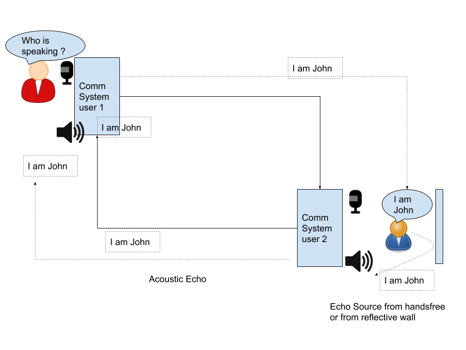
Echo is the sound of your own voice reverberating. If the amplitude of such a sound is high and intervals exceed 25 ms, it becomes disruptive to the conversation. Its types can be acoustic or hybrid. Echo cancellers need to eliminate the echo while still preserving call quality and not disrupting tones such as DTMF.

Acoustic Echo 

Usually the background or reflected noise which is an undesired voiceband energy transfers from the speaker to the microphone and into the communication network. Mostly found in a hands-free set or speakerphone. In a multiparty call scenario, it could also occur due to unmatched volume levels, challenging network conditions on one party, background noise, double talk or even proximity between user and microphone

Hybrid / Electronic Echo in PSTN phones

In a public telephone system, local loop wiring is done using two-wire connections carrying bidirectional voice signals. In PBX, a two-to-four wire conversion is done using a hybrid circuit which does not perform perfect impedance matches resulting in a Hybrid echo.

echo AEC
Hybrid / Electronic Echo in PSTN phones

Echo Cancellation

An efficient echo canceller should cancel out the entire echo tail while not leading to any packet loss. It needs to be adaptive to changing IP network bandwidth and algorithm should function equally well in conference scenarios  where there may be more than one echo sources. Benchmarking tools like MOS (Mean Opinion scores ) are used to gauge the  results. Often voice quality enhancement technologies are also integrated into AEC modules, such as :

  • automatic Gain control ( AGC) ,
  • Noise Reduction
  • Confort Noise Generator ( CNG)
  • Non linear processor
  • tone Disabler for SS& and DTMF tones
echo AEC 2
Automatic Echo Cancellation

WebRTC Echo Cancellation

WebRTC now actively detects and removes echo especially the local system echo resonance.

Noise Suppression in WebRTC

Noise suppression automatically filters the audio to remove background noise.

Automatic Gain Control (AGC)

AGC works as a circuit. When the average audio level is low , circuit raises it and if the audio level is high the circuit brings it down.

  • (+) AGC frees the user from manually tuning the audio level.
  • (-) During a pause too , agc tries to bring audio level to standard setting making background noises louder.
  • (-) subesquent audio processing make gain control progressively worse.

Audio Compressor : Due to the drawbacks with AGC , Audio Compressers carry the operation more sophistically by looking at amplitude of the sound.

(-) not ideal for music which had varrying sound amplitude.

Audio Peak Limiter : Limiters simply keep the audio from exceeding a set maximum level.

(+) well suited for avoiding loud noise such as door slam from entering the processing pipeline.

Audio Expanders :increase the dynamic (loudness) range of audio that has been overly processed.

(+) suited for over compressed audio transmissiono such as Satellite relays

Audio Filters :attenuate audio frequencies either above or below certain points within the audio range.

AGC in webRTC

navigator.mediaDevices.getSupportedConstraints();

aspectRatio: true
autoGainControl: true
brightness: true
channelCount: true
colorTemperature: true
contrast: true
deviceId: true
echoCancellation: true
exposureCompensation: true
exposureMode: true
exposureTime: true
facingMode: true
focusDistance: true
focusMode: true
frameRate: true
groupId: true
height: true
iso: true
latency: true
noiseSuppression: true
pan: true
pointsOfInterest: true
resizeMode: true
sampleRate: true
sampleSize: true
saturation: true
sharpness: true
tilt: true
torch: true
whiteBalanceMode: true
width: true
zoom: true

WebRTC Get User MEdia with various values of autoGainControl

References :

VoIP API design

  • Public API endpoints
  • Internal API gateways
  • API Rate Limiter
    • Token based Rate Limiting
    • Token bucket filter
    • Hierarchical Token Bucket (HTB)
    • Fair Queing
    • CBQ (Class Based Queing)
    • Modular QoS command-Line interface (MQC) Shaping
  • Throttling

VoIP manages Call setup and teardown using IP protocol. The APIs can be used to provide public or internal endpoinst to create mnage calls , conference addon services like recording , tgranscription or even do auth and heartbeat. This article lists some external programmable Call Control APIs, internal APIs for biling , health as well as Rate limitting.

Public API endpoints

Programmatic call control APIs

  1. Making a Call

HTTP POST https://www.altteelcom.com/voice/call

Parameters

to: '+14155551212',
from: '+18668675310'

Calback params

statusCallback: 'https://www.myapp.com/events',
statusCallbackEvent: ['initiated', 'answered'],
statusCallbackMethod: 'POST'

Response

"from": "+9999999999"
"to": "+111111111",
"status": "ongoing"

Tmestamps
"date_created": "Mon, 5 Sep 2020 20:36:28 +0000"
"start_time": "Mon, 5 Sep 2020 20:36:29 +0000"
"date_updated": "Mon, 5 Sep 2020 20:36:44 +0000"
"direction": "outbound",
"duration": ""
"end_time": ""

Price
"price": "-0.03000"
"price_unit": "USD"

The response can additional have SID and app version and other URI for recording , transcription , apyment and other services for this call .

2. Ending an ongoing Call

HTTP UPDATE https://www.altteelcom.com/voice/call/callid001

params

status: 'end'

This updates the end time of the call and sets the evenst for CDR processing

Services API

  • Call Reording
  • Call transcription

Confernece APIs
HTTP POST https://www.altteelcom.com/voice/conferences

  • creating a conf
  • fetching conf based on date or room name
  • updating a ongoing conf
  • ending a conf
  • set IVR announcement on ongoing conf

Auth API

CDR APIs

HTTP POST https://www.altteelcom.com/cdr

  • get CDR ( filtered per cal or acc to specific date or account)
  • bulk export of CDR

Internal API gateways

API Rate Limiter

Noisy neighbour is when one of the clients monoplizes the bandwidth using most of the i/o or cpu or other resources which can negatively affect the performance for other users . Throttling is a good way to solve this problem by limit.

Auto scaling Load balancerRate Limiter
horizotal or vertical scalling can countger incoming trafficLB can limit number of simultaneous requests. It can reject or send to queue for later operationCan intelligently understand the cost of each operation and perform throttling.
(-) takes time to scale out thus cannot solve noisy neighbour problem immediately(-) but the LB’s behaviour is indiscriminate ( cannot distinguish between the cost of diff operations)
(-) LB cannot ensure uniform distribution of distribution of operations among all servers.

A rate limiter should have low latency, accurate and scalable.

RateLimiter inside the serviceprocessRate Limiter as its own process outside as a daemon
(+) faster , no IPC
(+) reisstnt to interprocess call failures
(+) programming langiage agnostic daemon
(+) uses its own memory space, more predictable
(-) service meory needs to allocate space for rate limiters
widely used for auto discovery of service host

Token based Rate Limiting

 provides admission contro

Token bucket filter

define a users quota in terms average rate and burst capacity

Hierarchical Token Bucket ( HTB)

 uses the deficit round-robin algorithm for fair queuing

Fair Queing

give paying users a bandwidth fraction of 25%

priority queuing

decide 1 packet/ms for free or reduce rate user

distributes that sender’s bandwidth among the other senders

CBQ ( Class Based Queing)

Shaping is performed using link idle time calculations based on the timing of dequeue events and underlying link bandwidth. Input classes that tried to send too much were restricted, unless the node was permitted to “borrow” bandwidth from a sibling.

Modular QoS command-Line interface (MQC) Shaping

mplement traffic shaping for a specific type of traffic using a traffic policy

  • When the rate of packets matching the specified traffic classifier exceeds the rate limit, the device buffers the excess packets.
  • When there are sufficient tokens in the token bucket, the device forwards the buffered packets at an even rate.
  • When the buffer queue is full, the device discards the buffered packets.

Throttling

  • delay the packet until the bucket is ready / shaping
  • drop the packet / Policing
  • mark the packet as non-compliant

Failure management on Rate Limiter

  • Node Crash : just less requests trolled
  • Leaky bucket
  • tokens can go into -ve

System Design for API gateway

Important points for design API gateway

  • Serialize data in company binary format
  • allocate buffer in memory and build frequency count hash table and flash once full or based on time to calculate counters
  • aggregation on API gateway on the fly
Frontend ServicePartitioned ServiceBackend Service
Lightweight web service
Stateless
Request Validation
Auth / Authorization
TLS(SSL ) termination
Server sode encryption
Caching
Rate Limiting(throttling)
Request deduplication
Caching layer between frontend and backend
Replication
Leader Selection + Quorem

Distributed messaging system( fast and slow paths) for API

A distributed messahing system such as Apache kafka or AWs kinesis, internally splits a msg accross serveral partitions where each parition can be placed on a single shard in a seprate machine on a clustered system.

Applications of this system design

  • Find heavy hitters ( Top K problem )
  • Popular products / trends
  • Voltaile stocks
  • DDoS Attack Prevention

References :
High availiability and Scalibility in VoIP platforms


Load Balancers

Load Balancer(LB) is the initial point of interaction between the client application and the core system. It is pivotal in the distribution of the load across multiple servers and ensuring the client is connected to the nearest VoIP/SIP application server to minimize latency. However, the load balancers are also susceptible to security breaches and DOS attacks as they have a public-facing interface. This section lists the protocols, types and algorithms used popularly in Load balancers of VoIP systems.

software LBLayer 4 / hardware LB
Nginx
Amazon ELB ( eleastic load balanecr)
F5 BIG-IP load balancer
CISCO system catalyst
Barracuda load balancer
NetScaler
used by applications in cloud
ADN (Application delivery network)
used by  network address translators (NATs) 
DNS load balancing
examples and roles of software and hardware based load balancers

Load Balancers(LB) ping each server for health status and greylists servers that are unhealthy( respond late) as they may be overloaded or experiencing congestion. The LB monitors it rechecks after a while and if a server is healthy ( ie if a server responds with responds with status update) it can resume sending traffic to it. LB should also be distributed to different data centres in primary-secondary setup for HA.

Networking protocol

TCP LoadbalancerHTTP load balancersSIP based LB as Kamailio/ Opensips
can forwrad the packet without inspecting the content of the packet.terminate the connection and look inside the request to make a load balcing decsiion for exmaple by using a cookie or a header.domain specific to VoIP
(+) fast, can handle million of req per second(+) handle SIP routing based on SIP headers and prevent flooding atacks and other malicious malformed packets from reaching application server

Load balancing algorithms

  • Weighted Scheduling Algorithm
  • Round Robin Algorithm
  • Least Connection First Scheduling
  • Lest response time algorithms
  • Hash based algorithm ( send req based on hashed value such as suing IP address of request URL)
LoadbalancerReverse Proxy
forward proxy server allows multiple clients to route traffic to an external serveraccepts clients requestd for server and also returns the server’s response to the client ie routes traffic on behalf of multiple servers.
Balances load and incoming traffic endpointpublic facing endpoint for outgoing traffic
 additional level of abstraction and security, compression
used in SBC (session border controllers) and gateways

Service Discovery

Client-side or even backend service discovery uses a broadcasting or heartbeat mechanism to keep track of active servers and deactivates unresponsive or failed servers. This process of maintaining active servers helps in faster connection time. Some approaches to Service Discovery

  1. Mesh
    1. (-) exponentially incresing network traffic
  2. Gossip
  3. Distributed cache
  4. Coordination service with Service
    • (-) requesres coordination service for leader selection
    • (-) needs consensus
    • (-) RAFT and pbFT for mnaging failures
  5. Random leader selection
    • (+) quicker
    • (-) may not gurantee one leader
    • (-)split brain problem

Keepalive, unregistering unhealthy nodes

Systems such as Consul, Etcd, and Zookeeper can help services find each other by keeping track of registered names, addresses, and ports. Health checks help verify service integrity and are often done using an HTTP endpoint.

Replication

Usuallay there is a tradeoff between liveness and safety.

  1. Single leader replication
    • (-) vulnerable to loss of data is leader goes down before replication completes
    • used to in sql
  2. multileader replication and
  3. leaderless replication
    • (-) increases latencies
    • (-) quorem based on majority , cannot function is majority node are not down
    • used in cassandra

Data Store Replication

For Relatonal Dataabase

For NoSQL databse replication and HA

Quick Response / Low latency

Message format

Textual Message formatBinary Message Format
human readbale like
json xml
diff to comprehend , need shared schema between sender and receiver to serilaize and deserialze ,
names for every field adds to size no field name or only tags , reduces message size

Gateways for faster routing and caching to services

gateways are single entry point to route user requests to backend services .

Separate hot storage from cold storage

hot storage is frquently accessed data which must be near to server

cold storage is less frequently accessed data such as archives

  • object storage
  • slow access

Scalability

To make a system :-

  • scalable : use partitioing
  • reliable : use replication and checkpointing to not loose data in failures
  • fast : use in -memory usage

According to CAP theorem Consistency and Availiability are difficult to achieve together and there has to be a tradeof acc to requirnments.

Partitioining

Partition strategy can be based on various ways such as :-

  • Name based partition
  • geographic partition
  • names’ hashed value based on identifier
    • (-) can lead to hot partitions ( high density in areas of freq accessible identioers )
    • (-) high density spots for example all messages with a null key to go to the same partition
    • (-) doesnt scale
  • event time based hash
    • (+) data is spread evenly over time

To create a well distributed partition we could spread hot partition into 2 partitions or dedicate partitions for freq accessible items. An effective partitioning keys uses

  • Cardinality : total num of unique keys for a usecase. High cardinality leads to better distribution.
    • high cardinatility keys : names , email address , url since they have high variatioln
    • low cardinatlity keys : boolean flags such as gender M/F
  • Selectivity : number of message with each key. High selectivity leads to hotspots and hence low selectivity is better for even distribution.

Autoscalling

Scale Out not Up !

Kubernetes is an open-source container-orchestration system for automating computer application deployment, scaling, and management used in DevOps. I have mentioned this in detail on the article on VoIP and DevOps below.

Multiple PoPs (point of presence)

for a VOIP system catering to many clients accross the globe or accessing multiple carriers meant for different counteries based on Prefix matching , there should be alocal PoP in most used regions . typically these regions include – US east – west coasts, UK – germany of London , Asia Pacific – Mumbai ,Hong Kong and Australia.

Minimal Latency and lowest amount of tarffic via public internet

Creating multiple POPs and enabling private traffic via VPN in between them ensures that we use the backbone of our cloud provider such as AWS or datacentre instead of traversing via public internet which is slower and more insecure. Hopping on a private interface between the cloud server and maintaining a private connection and keepalive between them helps optimize the traffic flow while keeping the RTT and latency low.

HA ( High-availability )

Some factors affecting Dependability are

  • Eventual Consistency
  • MultiRegion failover
  • Disaster Recovery

A high-availability (HA) architecture implies Dependability.Usually via existence of redundant applications servers for backups: a primary and a standby. These applications are configured so that if primary fails, the other can take over its operations without significant loss of data or impact to business operations.

Downtime / SLA of 5 9’s in aggregate failures

4 9’s of availiability on each service components gives a downtime of 53 mins per service each year. However in aggregate failure this could amlount to (99.99)10 = 99.9 downtime which is 8-10 hours each year.

Thus, aggregate failure should be taken into consideration while designing reliable systems.

HA for Proxy / Load balancer (LB)

A LB is the first point of contact for outbound calls and usually does not save the dialogue information into memory or database but still contain the transaction information in memory. In case the LB crashes and has to restart, it should

  • have a quick uptime
  • be able to handle in dialogue requests
  • handle new incoming dialogue requests in a stateless manner
  • verify auth/authorization details from requests even after restart

HA for Call Control app server

App server is where all the business logic for call flow management resides and it maintains the dialog information in memory.

Issues with in-memory call states : If the VM or server hosting the call control app server is down or disconnected, then live calls are affected, this, in turn, causes revenue loss. Primarily since the state variable holding the call duration would be able to pass onto the CDR/ billing service upon the termination of the call. For long-distance, multi telco endpoint calls running hours this could be a significant loss.

  • Standby app server configuration and shared memory : If the primary app server crashes the standby app server should be ready to take its place and reads the dialog states from the shared memory.
  • Live load balanced secondary app server + external cache for state varaibles : External cache for state variables: a cluster of master-slave caches like Redis is a good way of maintaining the dialogue state and reading from it once the app server recovers from a failed state or when a secondary server figures it has a missing variable in local memory.

Media Server HA

Assuming the kamailio-RTPengine duo as App server and Media Server. These components can reside in same or different VMs. Incase of media server crash, during the process of restoring restarted RTpengine or assigning a secondary backup RTpengine , it should load the state of all live calls without dropping any and causing loss of revenue . This is achived by

  • external cache such as Redis ,
  • quick switchover from primary to secondary/fallback media server and
  • floating IPs for media servers that ensures call continuity inspite of failure on active media server.

Architecturally it looks the same as fig above on HA for the SIP app server.

Security against malicious attacks

Attacks and security compromisation pose a very signficant threat to a VoIP platform.

MITM attacks

Man in midddle attacks can be counetred by

  • End to end encryption of media using SRTP and signals using TLS
  • Strong SIP auth mechanism using challenges and creds where password is composed of mixed alphanumeric charecters and atleast 12 digits long
  • Authorization / whitelisting based on IP which adheres to CIDR notation

DDOS attacks

DDOS renders a particular network element unavailable, usually by directing an excessive amount of network traffic at its interfaces.

dDOS – multiple network hosts to flood a target host with a large amount of network traffic. Can be created by sending falsified sip requests to other parties such that numerous transactions originating in the backwards direction comes to the target server created congestion.

Can be counetred by

  • detect flooding and q in traffic and use Fail2ban to block
  • challenge questionable requests with only a single 401 (Unauthorized) or 407 (Proxy Authentication Required)

Read about SIP security practices in deatils https://telecom.altanai.com/2020/04/12/sip-security/

Other important factors leading to security

  • Keystores and certificate expiry tracker
  • priveligges and roles
  • Test cases and code coverage
  • Reviewers approval before code merge
  • Window for QA setup and testing , to give go ahead before deployment

Identifying outages and Alerting

Raise Event notification alerts to designated developers for any anolous behavior. It could be call based or SMS basef alert based on the sevirity of the situtaion .

Logging and Alerting for a VoIP CPaaS platform .
Raise Event notification alerts to designated developers for any anolous behavior. It could be call based or SMS basef alert based on the sevirity of the situtaion.

Sources for alert manager

  • Build failed ( code crashes, Jenkins error)
  • Deployment failed ( from Kubernetes , codechef, docker ..)
  • configuration errors ( setting VPN etc )
  • Server logs
  • Server health
  • homer alerts ( SIP calls responses 4xx,5xx,6xx)
  • PCAP alerts ( Malformed SIP SDP ..)
  • Internal Smoke test ( auto testing procedure done routinely to check live systems )
  • Support tickets from customer complaints ( treat these as high priority since they are directly impacting customers)

Bottlenecks

The test bed and QA framework play a very crticial role in final product’s credibility and quality.

Performance Testing

  • Stress Testing : take to breaking
  • Load Testing : 2x to 3x testing
  • Soak Testing : typical network load to long time ( identify leaks )

Robust QA framework( stress and monkey testing) to identify potential bottlenecks before going live

A QA framework basically validates the services and callflows on staging envrionment before pushing changes to production. Any architectural changes should especially be validated throughly on staginng QA framework befire making the cut. The qualities of an efficient QA platform are :

Genric nature – QA framework should be adatable to different envrionments such as dev , staging , prod

Containerized – it should be easy to spn the QA env to do large scale or small scale testing and hence it should be dockerized

CICD Integration and Automation – integrate the testcases tightly with gt post push and pull request creation . Minimal Latency and lowest amount of tarffic via public internet

Keep as less external dependecies as possible for exmaple a telecom carrier can be simulated by using an PBX like freeswitch or asterix

Asynchronous Run – Test cases should be able to run asynchronously. Such as seprate sipp xml script for reach usecase

Sample Testcases for VoIP

  • Authentication before establish a session
  • Balance and account check before establishing a session like whitelisting , blacklisting , restricted permission in a particular geography
  • Transport security and adaptibility checks , TLS , UDP , TCP
  • codec support validation
  • DTMF and detection
  • Cross checking CDR values with actual call initiator and terminator party
  • cross checking call uuid and stats
  • Validating for media and related timeouts

QA frameworks tools – Robot framework

traffic monitor – VOIP monitor

customer simulator – sipP scripts

network traffic analyser – wireshark

pcap collevcter – tcpdump , sngrep

Distributed Data Store

A Distributed Database Design could have many components. It could work on static datastore like

  • SQL DB where schema is important
    • MySQL
    • postgress
    • Spanner – Globally-distributed database from Google
  • NoSQL DB for to store records in json
    • Cassandra – Distributed column-oriented database
  • Cache for low latency retrivals
    • Memcached – Distributed memory caching system
    • Redis – Distributed memory caching system with persistence and value types
  • Data lakes for heavy sized data
    • AWS s3 object storage
    • blob storage
  • File System
    • Google File System (GFS) – Distributed file system
    • Hadoop File System (HDFS) – Open source Distributed file system

or work on realtime data streams

  • Batch processing ( Hadoop Mapreduce)
  • Stream processing ( Kafka + spark)
    • Kafka – Pub/sub message queue
  • Cloud native stream processing ( kinesis)

Each component has its own pros and cons. The choice depends on requirnments and scope for system behaviour like

  • users/customer usuage and expectation ,
  • Scale ( read and write )
  • Performnace
  • Cost
Users/customersScale ( read / write)PerformanceCost
Who uses the system ?
How the system will be used?
Read / writes per second ?
Size of data per request ?
cps ( calls or click per second) ?
write to read delay ?
p99 latency for read querries ?
should design minimize the cost of development ?

should design mikn ize the cost of mantainance ?
spikes in traffic eventual consistency ( prefer quick stale data ) as compared to no data at all
redundancy for failure management

Some fundamental constrains while design distributed data structure :-

p99 latency : 99% of the requests should be faster than given latency. In other words only 1% of the requests are allowed to be slower.

Request latency:
    min: 0.1
    max: 7.2
    median: 0.2
    p95: 0.5
    p99: 1.3

Inidiviual Events vs Aggregate Data

Inidividual Events ( like every click or every call metric)Aggregate Data ( clicks per minute, outgoing calls per minute)
(+) fast write
(+) can customize/ recalculate data from raw
(+) faster reads
(+) data is fready for decision making / statistics
(-) slow reads
(-) costlier for large scale implementations ( many events )
(-) can only query in the data as was aggregates ( no raw )
(-) requires data aggregation pipeline
(-) hard to fix errors
suitable for realtime / data on fly
low expected data delay ( minutes )
suitable for batch processing in background where delay is acceptable from mintes to hours

Push vs Pull Architecture

Push : A processing server manages state of varaible in memory and pushes them to data store.

  • (-) crashed processingserver means all data is lost

Pull : A temporary data strcyture such as a queue manages the stream of data and processing service pull from it to process before pusging to data stoore.

  • (+) a crashed server has to effect on temporarily queue held data and new server can simply take on where previous processing server left.
  • (+) can use checkpointing
SQLNoSQL
Structured and Strict schema
Relational data with joins
Semi-structured data
Dynamic or flexible schema
(+) faster lookup by index(-) data intensive workload
(+) high throughput for IOPS (Input/output operations per second )
used for
Account information
transactions
best suitable for
Rapid ingest of clickstream and log data
Leaderboard or scoring data
Metadata/lookup tables
DynamoDB – Document-oriented database from Amazon
MongoDB – Document-oriented database

A NoSQL databse can be of type

  • Quorem
  • Document
  • Key value
  • Graph

Cassandra is wide column supports asyn master less replication

Hinge base also a quorem based db also has master based preplication

MongoDB documente orientd DB used leacder based replication

SQL scaling patterns include:

  • Federation/ federated database system : transparently maps multiple autonomous database systems into a single virtual/federated database.
    • (-) slow since it access multiple data storages to get the value
  • Sharding / horizontal partition
  • Denormalization : Even though normalization is more memory efficient denormalization can enhance read performance by additing redundant pre computed data in db or grouping related data.
    • Normalizing data reduces data warehouse disk space by reducing data duplication and dimension cardinality. In its full definition, normalization is the process of discarding repeating groups, minimizing redundancy, eliminating composite keys for partial dependency and separating non-key attributes.
  • SQL Tuning : “iterative process of improving SQL statement performance to meet specific, measurable, and achievable goals”

Influx DB : to store time series data

AWS Redshift

Apache Hadoop

Redis

Embeed Data : RocksDB

Message Queues(Buffering) vs Batch Processing

Distributed event management, monitoring and working on incoming realtime data instead of stored Database is the preferred way to churn realtime analysis and updates. The multiple ways to handle incoming data are

  1. Batch processing – has lags to produce results, not time crtical
  2. Data stream – realtime response
  3. Message Queues – ensures timely sequence and order
BufferingBatching
Add events to buffer that can be read Add events to batch and send when batch is full
(+) can handle each event(+) cost effective
(+) ensures throughput
(-) if some events in batch fail should whole batch fail ?
(-) not suited for real time processing
S3 like objects storage + Hadoop Mapreduce for processing

Timeout

  • Connection timeout : use latency percentiles to calculate this
  • Request timeout

Retries

  • exponential backoff : increase waiting time each try
  • jitter : adds rabdomness to retry intervals to spread out the load.

Grouping events into object storage and Message Brokers

slower than stream processing but faster than batch processing.

Distributed Event management and Event Driven architecture using streams

In event driven archietcture a produce components performs and action which creates an event thata consumer/listener would subscribes to consume.

  • (+) time sensitive
  • (+)Asynch
  • (+) Decoupled
  • (+) Easy scaling and Elasticity
  • (+) Heterogeneous
  • (+) contginious

Expanding the stream pipeline

Event Streams decouple the source and sink applications. The event source and event sinks (such as webhooks) can asynchronously communicate with each other through events.

Options for stream processing architectures

  • Apache Kafka
  • Apache Spark
  • Amazon kinesis
  • Google Cloud Data Flow
  • Spring Cloud Data Flow

Here is a post from earlier which discusses – Scalable and Flexible SIP platform building, Multi geography Scaled via Universal Router, Cluster SIP telephony Server for High Availability, Failure Recovery, Multi-tier cluster architecture, Role Abstraction / Micro-Service based architecture, Load Balancer / Message Dispatcher, Back end Dynamic Routing and REST API services, Containerization and Auto Deployment, Auto scaling Cloud Servers using containerized images.

Lambda Architecture

Stream processing on top of map reduce and stream processing engine. In lambda architecture we can send events to batch system and stream processing system in parallel. The results are stiched together at query time.

Lambda Archietcture : stream processing on top of map reduce and stream processing engine. Send events to batch system and stream processing system in parallel. The results are stiched together at query time.

Apache Kafka is used as source which is a framework implementation of a software bus using stream-processing. “.. high-throughput, low-latency platform for handling real-time data feeds”.

Apache Spark : Data partitioning and in memory aggregation.

Distributed cache for call control Servers

Dedicated Cache ClusterCo located cache
Isolates cache fro service
Cache and service do not share memory and CPU
can scale independently
can be used by many microservices
flexibility in choosing hardware
doesnt require seprate hardware
low operational and hardware cost
scales together with the service

Choosing cache host

  • Mod function
    • (-) behaves differently when a new client is added or one is removed , unsuitable for prod
  • Consistent hashing ( chord)
    • maps each value to a point on circle

Cache Replacement

Least Recently Used Cache Replacement

Consistency and High Availiability in Cache setup

ReadReplicas live in differenet data centre for disaster recovery.

Strong consistency using Master Slave

Circuits – fail fast, wait for circuit to recover before using again

Design patterns for a circuit base setup to gracefully handle exceptions using fallback.

Circuit breaker : stops client from repeatedly trying to exceute by calculate the error threshold.

Isolated thread pool in circuits and ensure full recovery before calling the service again.

(+) Circuit breaker event causes the entire circuit to repair itself before attempting operations.

References :

Software Defined Networks ( SDN) and Network Function Virtulaization ( NFV) for Communication networks


Innovations in telecommunication today are largely driven by the advancements in Open source tech tools, standards and stacks. IP-based video and voice communication systems, Unified Communication systems such as Enterprise CPaaS platforms or even an external independent VoIP provider. The challenge for service providers today is that operating costs are growing faster than revenues. A large number of growing systems and vendors make operation a complex and expensive process.

Discrepancies between traffic growth and revenue growth (Source: Accenture)

Maintaining a network for communication service providers can be a complex and challenging task for several reasons:

  1. Network maintenance and upgrades: Service providers must constantly maintain and upgrade their networks to ensure that they are able to provide reliable service to their customers. This can involve replacing outdated equipment, installing new technology, and troubleshooting issues that arise.
  2. Managing traffic: Service providers must manage the traffic on their networks to ensure that it is distributed efficiently and that users are able to access the services they need. This can be a challenge, especially when the network is congested or there are unexpected spikes in traffic.
  3. Ensuring security: Communication networks are vulnerable to a variety of security threats, including hacking, malware, and denial of service attacks. Service providers must take measures to protect their networks and their customers’ data from these threats.
  4. Managing costs: Maintaining a communication network can be expensive, and service providers must find ways to manage costs while still providing high-quality service to their customers.
  5. Meeting regulatory requirements: Service providers must comply with a variety of regulations, including those related to privacy, data protection, and network security. Failing to comply with these regulations can have serious consequences, including fines and reputational damage.

Network Virtualisation

Network virtualization is the process of creating a virtual version of a network, including the hardware, network topology, and protocols, using software. This allows multiple virtual networks to be created and run on the same physical infrastructure, which can be used to isolate different network environments, test new network configurations, or provide network resources as a service.

NV = NFV + SDN

  • NFV is SW-defined network functions with separation of HW and SW. Once network elements are SW-based, network HW can be managed as a pool of resources
  • SDN is Interconnecting Virtual Network Functions with separation of control and data plane. Orchestration together with SW domain

There are several ways to implement network virtualization, including using software-defined networking (SDN) technologies, which allow the network to be controlled and managed using software, and using virtualization technologies such as virtual LANs (VLANs) or virtual private networks (VPNs) to create isolated network segments within a larger network. In a virtualized network the setup network functionalities are SW-based over COTS HW. Multiple roles can be made over same HW.

Network Virtualisation for Telcos

Network Virtualisation is an opportunity to build mouldable networks and redefine the architecture to make the infrastructure uniform.Virtual network services lowered CAPEX. Lessening dependencies on proprietary hardware and dedicated appliances.

  • (+) Improves management of risk in a changing and ambiguous environment
  • (+) capacity alteration Network flexibility
  • (+) scalability
  • (+) Service provisioning speed
  • (+) holistic management:
  • (+) granular security

There are several approaches to network virtualization that service providers can use, including:

  1. Network Function Virtualization (NFV): NFV involves virtualizing network functions, such as routers, firewalls, and load balancers, and running them on standard servers or other off-the-shelf hardware using virtualization platforms like VMware or OpenStack.
  2. Software-Defined Networking (SDN): SDN involves separating the control plane (which determines how data is routed through the network) from the data plane (which carries the actual data). This allows the control plane to be more flexible and responsive to changes in the network.
  3. Virtual Private Network (VPN): A VPN allows service providers to create virtual private networks (VPNs) over the public Internet, allowing them to securely connect users to the resources they need.

Service providers can use network virtualization to reduce costs, increase flexibility, and improve the scalability and reliability of their networks. Managed Service Providers (MSPs) can use a single viewpoint and toolset to manage virtual networking, computing and storage resources. However, implementing network virtualization can also be complex and require significant investments in hardware, software, and training.

Software Defined Network (SDN)

A software-defined network (SDN) is a networking architecture that uses software provisioning interfaces to control and manage the flow of traffic in a network. In an SDN, the control plane, which determines how data is routed through the network, is separated from the data plane, which carries the actual data traffic.

The main benefit of an SDN is that it allows the control of the network to be abstracted from the underlying hardware. This makes it possible to use software to dynamically configure the network, rather than relying on fixed configurations that are set using hardware switches and routers. SDN allows network administrators to easily and quickly change the way that data is routed through the network, which can be useful in a variety of scenarios. For example, an SDN can be used to optimize the flow of traffic in a data center, or to quickly reconfigure a network in response to changing traffic patterns or security threats such as DDoS.

SDN planes

Image Credits : Shqip: Arkitektura SDN, 27 June 2021, From Wikimedia Commons, the free media repository Source https://www.researchgate.net/publication/332970813_Security_for_5G_and_Beyond
  1. Control plane: The control plane is the part of the SDN that determines how data is routed through the network. It consists of a central controller, which is a software application that runs on a server, and a series of software agents that run on the network devices (such as switches and routers). The controller communicates with the agents using a protocol such as OpenFlow, which allows it to control the flow of traffic in the network.
  2. Data plane: The data plane is the part of the SDN that carries the actual data traffic. It consists of the network devices (such as switches and routers) that forward data packets through the network.
  3. Management plane: The management plane is the part of the SDN that is responsible for configuring and managing the network. It consists of a set of tools and applications that allow network administrators to monitor and control the network.
  4. Application plane: The application plane is the part of the SDN that consists of the applications that run on the network. These applications may include things like web servers, email servers, and database servers.

Software-defined network functions separates hardware and software. Once network elements are Software-based, network harware can be managed as a pool of resources. Separating route/switching intelligence from packet forwarding reduces hardware prices as routers and switches must compete on price-performance features.

SDN interconnects Virtual Network Function and orchestrated with SW domain. Enables separation of control and data plane.Setting up networks in an SDN can be as easy as creating VM instances, and the way SDNs can be set up is a far better complement to VMs than plain old physical networks. SDNs enable “network experimentation without impact”. Overcome SNMP limitations and experiment with new network configurations without being hamstrung by their consequences.

  • Infrastructure Savings
  • Reducing margin of Error : By eliminating manual intervention, SDNs enable resellers to reduce configuration and deployment errors that can impact the network.
  • Operational Savings: SDNs lower operating expenses. Network services can be packaged for application owners, freeing up the networking team.
  • Flexibility: SDNs create flexibility in how the network can be used and operated. Resellers can write their own network services using standard development tools.
  • Better Management gives Better visibility into the network, computing, and storage

SDN protocols : OpenFlow, NETCONF. Its applications could be

  • Bandwidth on Demand or test networks.
  • Platform Virtualization for emulation/simulation of Network Nodes (BSS/MSS)
  • SDN based Application Layer Traffic Optimization
  • Intrusion Detection System that can interact with controller in terms of capturing packets, analyzing them for anomaly and sharing results real-time / near real-time with controller.
  • Software-Defined Branch and SD-WAN
  • IP Multi-Media Subsystem (IMS)
  • Session Border Control (SBC)
  • Video Servers
  • Voice Servers
  • Universal Customer Premises Equipment (uCPE)
  • Content Delivery Networks (CDN)
  • Network Monitoring
  • Network Slicing
  • Service Delivery
  • Network security functions such as firewalls, IDS, IPS, vRR, NAT 

Network functions virtualization (NFV)

NFV provides the basic networking functions and SDN assumes higher-level management responsibility to orchestrate overall network operations.

blog.equinix.com/blog/2020/03/10/sdn-vs-nfv-understanding-their-differences-similarities-and-benefits/

Network Function Virtualization (NFV) is a technology that allows network functions, such as routers, firewalls, and load balancers, to be implemented in software rather than hardware. This allows these functions to be run on standard servers or other off-the-shelf hardware, rather than dedicated appliances.

In an NFV system, network functions are implemented as software called Virtual Network Functions (VNFs). These VNFs are run on virtualization platforms, such as VMware or OpenStack, which allow multiple VNFs to be run on the same physical hardware. To use NFV, a service provider will first define the network functions that it needs in its network, and then create VNFs for each of these functions. These VNFs can then be deployed on virtualization platforms and used to build the service provider’s network.

One of the main benefits of NFV is that it allows service providers to be more flexible and agile in building and managing their networks. Because VNFs can be easily added, removed, or scaled up or down as needed, service providers can quickly respond to changes in demand or new business opportunities. NFV decouples network functions from proprietary hardware appliances (routers, firewalls, VPN terminators, SD-WAN, etc.) and delivers equivalent network functionality without the need for specialized hardware. And this way it helps service providers reduce costs, as they can use standard hardware rather than specialized appliances ( vendor lockins) to implement their network functions.

IMS Virtual Network Functions (VNFs)

IMS. Image Credits Unknown

A traditional appliance based IMS setup is dedicated to every single service, limited hardware/people/process leveraging.Some drawbacks of this approach is

  • Not suited for Heterogeneous Networks that are evolving – inflexible
  • Higher footprint cost per customer/service – high OPEX
  • New services would need a new dedicated network thus high maintenance cost for solios of operation

Virtualisation will help to redesign the network architecture. In an IMS (IP Multimedia Subsystem) system, VNFs might be used to implement a variety of functions, including:

  1. Call Session Control Function (CSCF): The CSCF is responsible for managing call sessions and routing signaling messages between the IMS network and other networks.
  2. Media Gateway Control Function (MGCF): The MGCF is responsible for translating between different media formats, such as voice and video, and for controlling media gateways that connect the IMS network to other networks.
  3. Home Subscriber Server (HSS): The HSS is a database that stores information about IMS subscribers, including their profiles and service subscriptions.
  4. Serving Gateway (S-GW): The S-GW is responsible for routing data packets between the IMS network and the user’s device.
  5. Policy and Charging Rules Function (PCRF): The PCRF is responsible for enforcing policy decisions and charging rules for IMS services.
  6. IP-SM-GW (SMS Gateway): The IP-SM-GW is responsible for routing SMS messages between the IMS network and other networks.
  7. Presence Server: The presence server is responsible for managing presence information (such as availability status) for IMS subscribers.
Multi-tenant subscriber and service environment. Keeping traffic local but with common services & management

Local Data Centre can rapidly build Network Intelligence rationalisation using Real Time Network Analytics on virtul STB, EPC, NAT, BRAS, PE, DHCP , PCRF etc. Core can be simplified and centralised with common and standard interfaces within core network and services to interact with OSS and BSS (standardized billing and fulfillment process).

OpenStack

OpenStack is an open-source virtualization platform. It enables service providers to deploy virtual network functions (VNFs) using commercial off-the-shelf (COTS) server hardware.  OpenStack is widely used in the telecommunications industry, as it allows service providers to build and manage large-scale cloud computing environments that can be used to deliver a wide range of services, including virtualized infrastructure, NFV, and containerized applications. Applying Openstack to virtualize networks :

  1. Infrastructure as a Service (IaaS): OpenStack can be used to create and manage virtualized infrastructure, including compute, storage, and networking resources. This allows service providers to offer users the ability to spin up and manage virtual machines, storage volumes, and other resources on demand.
  2. Network Function Virtualization (NFV): OpenStack can be used as a platform for virtualizing network functions, such as routers, firewalls, and load balancers, and running them on standard servers or other off-the-shelf hardware.
  3. Container orchestration: OpenStack can be used to manage containerized applications, allowing service providers to deploy and scale applications more quickly and efficiently.
Image Credits OpenStack Wiki
Example of  OpenStack implementation. Image source: OpenStack Wiki

References:

More to read :

EEP (formely HEP) Extensible Encapsulation Protocol with HOMER

EEP duplicates and IP datagram and encapsulates and sends for remote relatime monitoring for SIP specific alerts and notifications . HEP is popular among many SIP servers including Freeswitch , Opensips, Kamailio, RTP engine as an external module .

  • intended for passive duplicated for remote collection
  • can be used for audit storage and analysis
  • does not alter the orignal datagram or headers

HOMER is Packet and Event capture system popular fpr VOIP/RTC Monitoring based on HEP/EEP (Extensible Encapsulation protocol)

SIP Server Integration

Homer and homer encapsulation protocl (HEP) integration with sip server brings the capabilities to SIP/SDP payload retention with precise timestamping better monitor and detect anomilies in call tarffic and events correlation of session ,logs , reports also the power to bring charts and statictics for SIP and RTP/RTCP packets etc. We read about sipcapture and sip trace modules in project sipcapture_siptrace_hep.

Both Kamailio and Opensips HEP Integration are structurally simmilar. In kamailio SIPCAPTURE [2] module enables support for –

● Monitoring/mirroring port
● IPIP encapsulation (ETHHDR+IPHDR+IPHDR+UDPHDR)
● HEP encapsulation protocol mode (HEP v1, v2, v3)

Figure Opensips Capturing ( credits http://www.opensips.org)

Figure showing Opensips integartion with external capturing agent via proxy agent ( which can be HOMER)

To achieve that, load and configure the SipCapture module in the routing script.

Snippets fro Kamailio Homer docker installation as a collector

git clone https://github.com/sipcapture/homer-docker.git
cd homer-docker
docker-compose build
docker-compose up

Outsnippets from screen while the installation takes place

Creating network "homer-docker_default" with the default driver
Creating volume "homer-docker_homer-data-semaphore" with default driver
Creating volume "homer-docker_homer-data-mysql" with default driver
Creating volume "homer-docker_homer-data-dashboard" with default driver
Pulling mysql (mysql:5.6)...
5.6: Pulling from library/mysql
...
Creating mysql ... done
Creating homer-webapp   ... done
Creating homer-cron      ... done
Creating homer-kamailio  ... done
Creating bootstrap-mysql ... done
Attaching to mysql, homer-webapp, bootstrap-mysql, homer-cron, homer-kamailio
....
homer-webapp | Homer web app, waiting for MySQL
homer-cron   | Homer cron container, waiting for MySQL
homer-kamailio | Kamailio, waiting for MySQL
bootstrap-mysql | Mysql is now running.
bootstrap-mysql | Beginning initial data load....
bootstrap-mysql | Creating Databases...
bootstrap-mysql | Creating Tables...
.....
omer-kamailio | Kamailio container detected MySQL is running & bootstrapped
homer-kamailio |  0(22) INFO: <core> [core/sctp_core.c:75]: sctp_core_check_support(): SCTP API not enabled - if you want to use it, load sctp module
homer-kamailio |  0(22) WARNING: <core> [core/socket_info.c:1315]: fix_hostname(): could not rev. resolve 0.0.0.0
homer-kamailio | config file ok, exiting...
homer-kamailio | loading modules under config path: //usr/lib/x86_64-linux-gnu/kamailio/modules/
homer-kamailio | Listening on 
homer-kamailio |              udp: 0.0.0.0:9060
homer-kamailio | Aliases: 
homer-kamailio | 
homer-kamailio |  0(23) INFO: <core> [core/sctp_core.c:75]: sctp_core_check_support(): SCTP API not enabled - if you want to use it, load sctp module
homer-kamailio |  0(23) WARNING: <core> [core/socket_info.c:1315]: fix_hostname(): could not rev. resolve 0.0.0.0
homer-kamailio | loading modules under config path: //usr/lib/x86_64-linux-gnu/kamailio/modules/
homer-kamailio | Listening on 
homer-kamailio |              udp: 0.0.0.0:9060
homer-kamailio | Aliases: 
homer-kamailio | 
homer-kamailio |  0(23) INFO: sipcapture [sipcapture.c:480]: parse_table_names(): INFO: table name:sip_capture
...
homer-webapp | Homer web app container detected MySQL is running & bootstrapped
homer-webapp | Module php5 already enabled

Capture tools

Dialoge module

storing dialogs in mysql DB , requires initialising mysql

#!define WITH_MYSQL
...
#!ifdef WITH_MYSQL
loadmodule "db_mysql.so"
#!endif
...
#!ifdef WITH_MYSQL
# - database URL - used to connect to database server by modules such
#       as: auth_db, acc, usrloc, a.s.o.
#!ifndef DBURL
#!define DBURL "mysql://root:kamailio@localhost/kamailio"
#!endif
#!endif
loadmodule "dialog.so"
# ----- dialog params ------
modparam("dialog", "dlg_flag", 10)
modparam("dialog", "track_cseq_updates", 0)
modparam("dialog", "dlg_match_mode", 2)
modparam("dialog", "timeout_avp", "$avp(i:10)")
modparam("dialog", "enable_stats", 1)
modparam("dialog", "db_url", DBURL)
modparam("dialog", "db_mode", 1)
modparam("dialog", "db_update_period", 120)
modparam("dialog", "table_name", "dialog")

seting db_mode – synchronisation of dialog information from memory to an underlying database has following options
0 – NO_DB – the memory content is not flushed into DB;
1 – REALTIME – any dialog information changes will be reflected into the database immediately.
2 – DELAYED – the dialog information changes will be flushed into DB periodically, based on a timer routine.
3 – SHUTDOWN – the dialog information will be flushed into DB only at shutdown – no runtime updates.

note :

  • use the same hash_size while using diff kamailio to restore dialogs

database table for dialogue

  1. install mysql
  2. define root ( with db create permissions ) and user ( with database read wrote ) permission in kamctlrc
vi /usr/local/etc/kamailio/kamctlrc
  • Dialogue table schema *
name type size default null key extra attributes description
id unsigned int 10 no primary autoincrement unique ID
hash_entry unsigned int 10 no Number of the hash entry in the dialog hash table
hash_id unsigned int 10 no The ID on the hash entry
callid string 255 no Call-ID of the dialog
from_uri string 128 no URI of the FROM header (as per INVITE)
from_tag string 64 no identify a dialog, which is the combination of the Call-ID along with two tags, one from participant in the dialog.
to_uri string 128 no URI of the TO header (as per INVITE)
to_tag string 64 no identify a dialog, which is the combination of the Call-ID along with two tags, one from participant in the dialog.
caller_cseq string 20 no Last Cseq number on the caller side.
callee_cseq string 20 no Last Cseq number on the caller side.
caller_route_set string 512 yes Route set on the caller side.
callee_route_set string 512 yes Route set on on the caller side.
caller_contact string 128 no Caller's contact uri.
callee_contact string 128 no Callee's contact uri.
caller_sock string 64 no Local socket used to communicate with caller
callee_sock string 64 no Local socket used to communicate with callee
state unsigned int 10 no The state of the dialog.
start_time unsigned int 10 no The timestamp (unix time) when the dialog was confirmed.
timeout unsigned int 10 0 no The timestamp (unix time) when the dialog will expire.
sflags unsigned int 10 0 no The flags to set for dialog and accesible from config file.
iflags unsigned int 10 0 no The internal flags for dialog.
toroute_name string 32 yes The name of route to be executed at dialog timeout.
req_uri string 128 no The URI of initial request in dialog
xdata string 512 yes Extra data associated to the dialog (e.g., serialized profiles).

Siptrace module

SIPtrace module offer a possibility to store incoming and outgoing SIP messages in a database and/or duplicate to the capturing server (using HEP, the Homer encapsulation protocol, or plain SIP mode).

loadmodule "siptrace.so"
modparam("siptrace", "duplicate_uri", "sip:127.0.0.1:9060")
modparam("siptrace", "hep_mode_on", 1)
modparam("siptrace", "trace_to_database", 0)
modparam("siptrace", "trace_flag", 22)
modparam("siptrace", "trace_on", 1)

integrating iut with request route to start duplicating the sip messages

sip_trace();
setflag(22);

  • trace_mode * 1 – uses core events triggered when receiving or sending SIP traffic to mirror traffic to a SIP capture server using HEP 0 – no automatic mirroring of SIP traffic via HEP.

duplicate

address in form of a SIP URI where to send a duplicate of traced message. It uses UDP all the time.

modparam("siptrace", "duplicate_uri", "sip:127.0.0.1:9060")

to check the duplicate messages arriving

ngrep -W byline -d any port 9060 -q

RPC commands

Can ruen sip trace on or off

kamcmd> siptrace.status on   
Enabled

and to check

kamcmd> siptrace.status check
Enabled

Store sip_trace in database

modparam("siptrace", "trace_to_database", 1)
modparam("siptrace", "db_url", DBURL)
modparam("siptrace", "table", "sip_trace")

where the sip_trace tabel description is

+-------------+------------------+------+-----+---------------------+----------------+
| Field       | Type             | Null | Key | Default             | Extra          |
+-------------+------------------+------+-----+---------------------+----------------+
| id          | int(10) unsigned | NO   | PRI | NULL                | auto_increment |
| time_stamp  | datetime         | NO   | MUL | 2000-01-01 00:00:01 |                |
| time_us     | int(10) unsigned | NO   |     | 0                   |                |
| callid      | varchar(255)     | NO   | MUL |                     |                |
| traced_user | varchar(128)     | NO   | MUL |                     |                |
| msg         | mediumtext       | NO   |     | NULL                |                |
| method      | varchar(50)      | NO   |     |                     |                |
| status      | varchar(128)     | NO   |     |                     |                |
| fromip      | varchar(50)      | NO   | MUL |                     |                |
| toip        | varchar(50)      | NO   |     |                     |                |
| fromtag     | varchar(64)      | NO   |     |                     |                |
| totag       | varchar(64)      | NO   |     |                     |                |
| direction   | varchar(4)       | NO   |     |                     |                |
+-------------+------------------+------+-----+---------------------+----------------+

sample databse storage for sip traces

select * from sip_trace;

| id | time_stamp          | time_us | callid  | traced_user | msg         | method | status | fromip                   | toip                     | fromtag  | totag    | direction |
+----+---------------------+---------+---------------------------------------------+-------------+-----------------------------------
|  1 | 2019-07-18 09:00:18 |  417484 | MTlhY2VmNDdjN2QxZGM5ZDFhMWRhZThhZDU4YjE0MGM |             | INVITE sip:altanai@sip_addr;transport=udp SIP/2.0
Via: SIP/2.0/UDP local_addr:25584;branch=z9hG4bK-d8754z-1f5a337092a84122-1---d8754z-;rport
Max-Forwards: 70
Contact: <sip:derek@call_addr:7086;transport=udp>
To: <sip:altanai@sip_addr>
From: <sip:derek@sip_addr>;tag=de523549
Call-ID: MTlhY2VmNDdjN2QxZGM5ZDFhMWRhZThhZDU4YjE0MGM
CSeq: 1 INVITE
Allow: INVITE, ACK, CANCEL, OPTIONS, BYE, REFER, NOTIFY, MESSAGE, SUBSCRIBE, INFO
Content-Type: application/sdp
Supported: replaces
User-Agent: Bria 3 release 3.5.5 stamp 71243
Content-Length: 214

v=0
o=- 1563440415743829 1 IN IP4 local_addr
s=Bria 3 release 3.5.5 stamp 71243
c=IN IP4 local_addr
t=0 0
m=audio 59814 RTP/AVP 9 8 0 101
a=rtpmap:101 telephone-event/8000
a=fmtp:101 0-15
a=sendrecv                                                                                                                                                                                      | INVITE |        | udp:caller_addr:27982 | udp:sip_pvt_addr:5060   | de523549 |          | in        |

|  2 | 2019-07-18 09:00:18 |  421675 | MTlhY2VmNDdjN2QxZGM5ZDFhMWRhZThhZDU4YjE0MGM |             | SIP/2.0 100 trying -- your call is important to us
Via: SIP/2.0/UDP local_addr:25584;branch=z9hG4bK-d8754z-1f5a337092a84122-1---d8754z-;rport=27982;received=caller_addr
To: <sip:altanai@sip_addr>
From: <sip:derek@sip_addr>;tag=de523549
Call-ID: MTlhY2VmNDdjN2QxZGM5ZDFhMWRhZThhZDU4YjE0MGM
CSeq: 1 INVITE
Server: kamailio (5.2.3 (x86_64/linux))
Content-Length: 0                                                                                                                                                                                                                                                                                                                                                                                                                                                           | ACK    |        | udp:caller_addr:27982 | udp:local_addr:5060   | de523549 | b2d8ad3f | in       |
...
+----+---------------------+---------+---------------------------------------------+-------------+-----------------------------------

Heplify

Multi-Protocol Go HEP Capture Agent made   https://github.com/sipcapture/heplify

wget https://dl.google.com/go/go1.11.2.linux-amd64.tar.gz
sudo tar -C /usr/local -xzf go1.11.2.linux-amd64.tar.gz

move package to /usr/local/go

mv go 

Either add go bin to ~/.profile

export PATH=$PATH:/usr/local/go/bin

and apply

source ~/.profile

or set GO ROOT , and GOPATH

export GOROOT=/usr/local/go
export GOPATH=$HOME/heplify
export PATH=$GOPATH/bin:$GOROOT/bin:$PATH

installation of dependencies

go get

clone heplify repo and make

make 

CAPTAGENT

New OSS Capture-Agent framework with capture suitable for SIP, XMPP and more. With internal method filtering , encryption and authetication this does look very promising howevr since I have perosnally not tried it yet , I will leave this space TBD for future

sngrep

https://github.com/irontec/sngrep

Other include Sipgrep , HEPipe and nProbe

HEPop

Multi-Protocol HEP Server & Switch in NodeJS. stand-alone HEP Capture Server designed for HOMER7 capable of emitting indexed datasets and tagged timeseries to multiple backends

https://github.com/sipcapture/HEPop

node hepop.js -c /app/myconfig.js

PCAP monitoring -> Homer Server -> Notification and Fraud Prevention

A realtime monitoring and alerting setup fom homer can best safeguard on VoIP specific attacks and suspecious activity by early warning . Some list of attacks such as DDOS , SIP SQL injections , parser , remote manipulation hijacking as cell as resource enumeration are common ifor a cloud telephony provider.

Adiitionally homer provide session quality using varables that include [1]

SD = Session Defects
[SUM(500,503,504)]

ISA = Ineffective Session Attempts
[SUM(408,500,503)]

AHR = Average HOP Requests

ASR = Answer Seizure Ratio
[(‘200’ / (INVITES – AUTH – SUM(3XX))) * 100]

NER = Network Efficiency Ratio
[(‘200’ + (‘486′,’487′,’603’) / (INVITES -AUTH-(SUM(30x)) * 100]

HOMER Web Interface or Custom Dashboard

Some more visualization for inter team communication such as NOC team can include

Homer Integration with influx DB

time series Reltiem DB install

wget https://dl.influxdata.com/influxdb/releases/influxdb_1.7.7_amd64.deb
sudo dpkg -i influxdb_1.7.7_amd64.deb

start

 >influxd
 8888888           .d888 888                   8888888b.  888888b.
   888            d88P"  888                   888  "Y88b 888  "88b
   888            888    888                   888    888 888  .88P
   888   88888b.  888888 888 888  888 888  888 888    888 8888888K.
   888   888 "88b 888    888 888  888  Y8bd8P' 888    888 888  "Y88b
   888   888  888 888    888 888  888   X88K   888    888 888    888
   888   888  888 888    888 Y88b 888 .d8""8b. 888  .d88P 888   d88P
 8888888 888  888 888    888  "Y88888 888  888 8888888P"  8888888P"

2019-07-19T07:03:04.603494Z	info	InfluxDB starting	{"log_id": "0GjGVvbW000", "version": "1.7.7", "branch": "1.7", "commit": "f8fdf652f348fc9980997fe1c972e2b79ddd13b0"}
2019-07-19T07:03:04.603756Z	info	Go runtime	{"log_id": "0GjGVvbW000", "version": "go1.11", "maxprocs": 1}
2019-07-19T07:03:04.707567Z	info	Using data dir	{"log_id": "0GjGVvbW000", "service": "store", "path": "/var/lib/influxdb/data"}

For Kamailio integration follow github instructions on https://github.com/altanai/kamailioexamples

References :

[1] https://www.kamailio.org/events/2013-KamailioWorld/13-Alexandr.Dubovikov-Homer-SIP-Capture.pdf

[2] HEP/EEP – https://github.com/sipcapture/hep

[3] kamailio sipdump module – https://www.kamailio.org/docs/modules/devel/modules/sipdump.html

[4] https://github.com/sipcapture/HEPop

[5] HOMER Big Data – https://github.com/sipcapture/homer/wiki/Homer-Bigdata

Energy Efficient VoIP systems

Data Centres are the concentrated processing units for the amazing Internet that is driving the technological innovation of our generation and has become the backbone of our global economy. DataCentres not only process , store and carry textual data rather a vast amount of computing is for multimedia content which could range from social media to, video streaming or VoIP calls. In this article let us analyze the energy effiiciency , carbon footprint and scope of improvements for a VoIP related data centre which hosts SIP and related RTC technology signalling and media servers and process CDRs and/or media files for playback or recordings.

Just like a regular IT datacentre , storage, computing power and network capacity define the usage of the server.Also unobstructed electricty of of paramount importance as any blackout could drop ongoing calls and lead to loss of revenue for the service provider not to forget the loss caused to parties engaged in call.

Increasing Power consumption by telecom Sector over the years

Global PPA(power purchase agreements) volumes by sector, 2009-2019, IEA, Global PPA volumes by sector, 2009-2019, IEA, Paris https://www.iea.org/data-and-statistics/charts/global-ppa-volumes-by-sector-2009-2019
source : CDP The 3% solution 2013 [19]

Typical VoIP Setup : Whether a cloud Infrstrcture provider of a hosted data centre , an aproximate number of 7 servers is required even for SME ( small to medium enterprises ) communication system and VoIP systems

  • 2 signalling servers primary and standby for HA ,
  • 2 media server for MCU of media bridges or IVR playback etc ,
  • 1 for CDR , logs or call analytics , stats and other supplementary operation
  • 1 for dev or engineering team .
  • 1 edge server could be API server or a gateway or laodbalancer.
Sample voIP system

VoIP solutions are more energy expensive, unless aggressive power saving schemes are in place

Comparison of energy efficiency in PSTN and VoIP systems [14]

While PSTN and other hybrid scenarios relied on audio only communication the embedded systems involved took great pain to make then energy efficient which is not really the case with all digital and software based VoIP.

Power Consumption

Mobile phone :  Typical smartphone with 4,000mAh ( 4 Ah) battery that gets 1 full cycle of usage a day. Daily consumption =4Ah*3.7V=14.8 Wh

Laptop : With  14–15″ screen, a laptop can draw 60 watts power in active use depending on model. Runing 8 hours a day can be 60 * 8 = 480 Wh ( 0.480 kWh) energy consumed in a day.

Desktop PC : Runing at 50-60 Hz frequency , can upto draw 200 W power in active use. For 8 hours energy usage 200 * 8 = 1600 Wh ( 1.6 kWh ) energy a day.

Server : Even though servers are virtual to the request maker , they caters to the request on the other end of the internet.

ServerPurposeServer CPU consumptionClientsClient CPU consumption
ApplicationHosts an application, which can be run through a web browser or customized client software.mediumAny network device with access.low
ComputingMakes available CPU and memory to the client. This type of server might be a supercomputer or mainframe.highAny networked computer that requires more CPU power and RAM to complete an activity.medium
DatabaseMaintains and provides access to any database.lowAny form of software that requires access to structured data.low
FileMakes available shared files and folders across a network.mediumAny client that needs access to shared resources.low
GameProvisions a multiplayer game environment.highPersonal computers, tablets, smartphones, or game consoles.high
MailHosts your email and makes it available across the network.mediumUser of email applications.low
MediaEnables media streaming of digital video or audio over a network.highWeb and mobile applications.high
PrintShares printers over a network.lowAny device that needs to print.low
WebHosts webpages either on the internet or on private internal networks.mediumAny device with a browser.medium
CPU consumption of various server types and their clients

Typically runing on 850 Wh ( 0.850 kwh ) of energy in an hour and since server are usually up 24*7 that totals to

0.850 * 24 = 20.4 kWh a day [2].

VoIP System ( 7 VM’s) : For a setup of 7 VM’s ( could on a the same PM), total energy consumed in a day

20.4 * 7 = 142.8 kWh.

Data centre: The data centre building consists of the infrastructure to support the servers, disks and networking equipment it contains. However, for simplicity, I will only use the consumption of servers and ignore the cooling units, networking, backup batteries charging, generators, lightning, fire suppression, maintenance etc.

High tier DC can have 100 Megawatts of capacity having each rack was using 25 kW of power in a 52U Rack. 100,000 kW / 25 kW = 4,000 racks * 52(U) = 208000 1U servers. This number scales down depending on how much energy each server uses and idle servers.

Total energy 100,000 kW * 24 hours = 2400000 kWh

Carbon Footprint

Carbon footprint in the context of this article refers to the amount of greenhouse gas ( consisting majorly of Co2) caused by electricity consumption. The unit is carbon emission equivalent of the total amount of electricity consumed kg CO2 per kWh.

In doing this calculation I have assumed 0.233 kg CO2 per kWh which could be less or more depending on the generation profile of the electricity provider as well as the heat produced by the machine.

Laptop: Aside from the production which could be 61.4 kg (135.5 lbs) of Co2, a 60W laptop will produce 0.112 kg co2 eq per day.

Desktop PC: Aside from production cost and heating, the GWG and co2 eq emission from running a desktop for a day ( 8 hours) produces 1.6* 0.233 = 0.3728 kg CO2 per kWh

Server : 20.4 * 0.233 = 4.7532 kg CO2 per kWh per day .

VoIP System ( 7 VM’s): Again ignoring the GWG emission of associated components, 142.8 * 0.233 = 33.2724 kg CO2 per kWh per day. It is to be noted that DC’s ( datacentres) use the term PUE ( Power Usage Effectiveness) to showcase their energy efficiency and energy efficiency certification uses the same in ratings.

Data centre: electrical carbon footprint( approximate calculation not counting the cooling, infra maintenance, lightning and possibly idle servers in datacentre) is 2400000 * 0.233 = 559200 kg CO2 per kWh per day

It is to be noted that a common figure should not be extrapolated like this to derive carbon emission. The emission depends on the fuel mix of the electricity generation as well as the life cycle assessment (LCA) of carbon equivalent emission. Countries with heavy reliance on renewables have lower co2 footprint per kWh ~ 0.013 kg co2 per kWh Sweden while others may have higher such as 0.819 kg CO2 per kWh Estonia [1].

Flatten the Curve from Tech and Internet usage

Rack servers tend to be the main perpetrators of wasting energy and represent the largest portion of the IT
energy load in a typical data center.

A decade ago, small enterprise IT facilities were quick to create data centres for hosting applications from hospitals, banks, insurance companies. While some of these is likely to have been upgrade to shared server instances runing on IaaS providers, most of them are still serving traffic or stays there for the lack of effort to upgrade.

With the advancement in p2p technlogies such as dApps , bitcoion network , p2p webrtc streaming , more edge computed ML continue to create disruptions in existing trend , most likely to result in in many fold increase in consumption.

According to the Cambridge Center for Alternative Finance (CCAF), Bitcoin currently consumes around 110 Terawatt Hours per year — 0.55% of global electricity production

Harward Business Review [12]

“the emissions generated by watching 30 minutes of Netflix (1.6 kg of CO2) is the same as driving almost four miles.” 

EnergyInnovation [13]

Cloud Computing and Energy efficiency

Cloud computing ( SaaS, PaaS , IaaS and also CPaaS) minimize power consumption and consequently IT costs via virtualization, clustering and dynamic configuration.

With cloud infrastrcture vendors such as Amazon , Google , microsoft .. and their adoption of energy efficiency computing and credible transparency has alleviated some of the stress that could have been made if onsite self – hosted data centres were used as often in mainstream as a decade ago.

Even as cloud providers gives on -demand access to shared resources in large scale distributed computing , the ease of getting on board has inturn created a surge in cloud hosted online applications consequently high power consumption, more operation costs and higher CO2 emissions.

Components of energy Consumption in Data Centre

As shown CPU, Memory, and Storage incur 45% of the costs and consume 26% of the total energy , however power distribution and colling cost 25% but consumer >50% of total energy.

Energy forcast for Data Centres

As reported by nature [3] the widely cited forcasts suggested thte total electrcity demand of ICT ( Informatioin and Communication technology ) will accelerate and while consumer devices such as smart TV , laptops and mobile are becoming energy effcient , the data centres and network devices will demand bigger portions. Reported in 2018 , 200 Twh( terawatt hours) of energy was being consumed by data centers . Although there are no figures for the telecom or specifically IP cloud telephony , the assumption that enormous multimedia data flows in every session is enouogh to assume the figure must be huge.

Energy eficiency in data centres have also been the subject of many papers and studies. Many of the tech advancements and measures have so far been able to keep the growth in energy requirnments by tech sector to a linear/ flat one.

past and projected growth rate of total US data center energy use from 2000 until 2020. It also illustrates how much faster data center energy use would grow if the industry, hypothetically, did not make any further efficiency improvements after 2010. (Source: US Department of Energy, Lawrence Berkeley National Laboratory)

Some noteworthy innovations made in Data centre for energy efficiency include –

  1. Star efficiency requirnments
  • Average server utilization
  • Server power scaling at low utilization
  • Average power draw of hard disk drives
  • Average power draw of network ports
  • Average infrastructure efficiency (i.e., PUE)

PUE = Total Facility power / IT equipment power

Standard 2.0, Good 1.4 , Better 1.1

Low PUE indicates greater efficicny since more power would then be used by It gear . Idealistically 1 should be the perfect score where all power was used only by the IT gears.

2. Optimizing the cooling system which takes a lot of focus is also not touched upon here but can be understood in great detail from very many sources including one here on how google uses AI for cooling its Datacentres [6]

3. Throttle-down drive ,a device that reduces energy consumption on idle processors, so that when a server is running at its typical 20% utilization it is not drawing full power

Energy efficiency is vital to not only productivity and performance but also to carbon neutral tech and economy. There is ample scope to designing energy efficient applications and platfroms. Some approaches are described below:

Energy Efficiency in VoIP Architecture and design

Low Energy consumption not only lowers operating cost but also helps the enviornment by reducing carbon emission.

1.Server Virtualization

By consolidating multiple independant servers to a single underlying physical server helps retain the logical sepration while also maintaining the energy costs and maximizinng utilization . VM’s( Virtual machines) are instances of virtaulized portions on the same server and can be independetly accesed using its own IP and network settings.

To reduce electricity usage in our labs and data centers, we use smart power distribution units to monitor
our lab equipment. We increase server utilization by using virtual machines. Our Cisco Customer
Experience labs use a check-in, check-out system of automation pods to allow lab employees to set up
configurations virtually and then release equipment when they are finished with it.

Cisco 2020 Environment Technical Review [20]

Models to place VMs on PM ( physical machine ) have been proposed by Dong et al[8] , Huang[9]  ,Tian et al [10]

2.Decommissioning old / outdated servers

While this is the most obvious way to increase efficiency , it is also the toughest since legacy applications or a small portion of it may be running on a server that service providers are not keen on updating or updates do not exist and it is past end of life yet somehow still in use. It is important to identify such components. Check if maybe an old glassfish or bea weblogic SIP servlet server needs updating and/or migration !

3.Plan HA ( high availability ) efficiently

Redundant servers take only if at all any , partial loads so they can be activated in full swing when failover happens in other server. With quick load up times and forward looking monitoring , the analyzers can monitor logs for upcoming failure or predictable downtime and infra script can bring up pre designed containers in seconds if not minutes. It isn’t wise to create more than 1 standby server which does no essential work but consumes as much power.

4.Consolidate individual applications on a Server

Map the maximum precitable load and deduce the percentage comsuption with teh same . In view of these figures it is best to consolidate applications servers to be run on a single server . A distributed microservice based architecture can also support consolidation by runing each major application in its own dockerized container. Consolidation ensures that

  • All data can be stored and accessed centrally, which reduces the likelihood of data duplication.
  • while a server is drawing full power , it is also showing relataible utilization.
  • Single point to prevent intrusion , provide security and fix vulnerabilities against malware like ( ransomware , viruses , spyware , trojans)

5.Reduce redundancy

While it is a common practise to store multiple copies of data such as CDR ( call detail records ) and archiev historical logs for later auditing , it is not the most energy efficient way since it ends up wasting stoarge space. It is infact a better approach to skim only the crtical parts and diacard the rest and definetely implement background tasks to compress the older and less referenced logs.

6.Power management

Powering down idle server or putting unused server to sleep is an effective way to reduce operating power but is often ignored by the IT department in view of risking slower performance and failure in call continuity in case a server does go down. However power management leads to potential energy savings and should be weighted accordingly.

7.Common Storage such as Network Attached Storage

Power consumption is roughly linear to the number of storage modules used. Storage redundancy needs to be
right-sized to avoid rapid consumption of avaible storage space , CPU cycles to refer and index them, its associated power consumption [7].

The process of maximizing storage capacity utilization by drawing from a common pool of shared storage on need baisis also allows for flexixbility.

It is sensible to take the data offline thereby reducing clutter on production system and make the existing data quickly retrievable.

8.Sharing other IT resources

Central Processing Units (CPU), disk drives, and memory optimizes electrical usage. Short term load shifting combined with throttling resources up and down as demand dictates improves long term hardware energy efficiency. [7]

Hardware based approaches such as energy star rating, air conditoning , placement of server racks , air flow , cabling etc have not been touched upon in this article they can be read from energystar report here [5] .

9. DMZ / Perimeter network

The perimeter network (also known as DMZ, demilitarized zone, and screened subnet) is a zone where resources and services accessible from outside the organization are available. Often used as barrier between internal secure green zone within company and outside partners / suppliers such as external organization gateways.

  • Load balancers
  • API gateways
  • SBC ( Session Border controllers)
  • Media Gateways

Ways to cut down on CPU consumption in DMZ machines

  1. Scrutinize incoming traffic only , trust outgoing traffic .

2. Use hardware / network firewalls to monitor and block instead of software defined ones . Hardware firewall can be a standalone physical device or form part of another device on your network. Physical devices like routers, for example, already have a built-in firewall. 

Other types of firewalls

  • Application-layer firewalls can be a physical appliance, or software-based, like a plug-in or a filter. These types of firewalls target your applications. For example, they could affect how requests for HTTP connections are inspected across each of your applications.
  • Packet filtering firewalls scrutinize each data packet as it travels through your network. Based on rules you configure, they decide whether to block the specific packet or not. For example firewalls can block SSH/RDP for remote management.
  • Circuit-level firewalls check whether TCP and UDP connections across your network are valid before data is exchanged. For example, this type of firewall might first check whether the source and destination addresses, the user, the time, and date meet certain defined rules.
  • Proxy server firewalls secure the traffic into and out of a network by monitor, filter, and cache data requests to and from the network.

Energy Efficiency in VoIP Applications and algorithms

In theory, energy efficient algorithms would take less processing power , run fewer CPU cycles and consume less memory. For the experiments with WebRTC and SIP VoIP systems CPU performance can be reliable factor to consider for carbon emissions . Here is list of approaches to include energy as of the parameters in programing for RTC applications.

  1. Take advanatge of Multi Core applications

Multi-core processor chips allow simultaneous processing of multiple tasks, which leads to higher efficiency. Same power source and shared cooling leads to better efficiency . It is the same logic which applied to consolidating one power supply for a rach isntead of individual power supply to each servers on rack.

2. Reduce Buffering

Input/Output buffer pile up comuted packets or blocks which will come inot use in near future but may be discarded all together in event of skip or shutdown. For example in case of video on Demand ( VoD) , a buffered video of 1 hour is of not much use if viewer decides to cancel the video session after 10 minutes .

3. Optimize memeory access algorithms

4. Network energy Management to vary as per demand

The newer generations of network equipment pack more throughput per unit of power. There are active energy management measures that can also be applied to reduce energy usage as network demand varies. In a telecoomunication system , almost always a tradeof between power consumption and network performance is made.

  1. Quick switching of speed of the network to match the amount of data that is currently transmitted. A demand following streaming session will maingtain the QoS , avoid imbalance while also reducing power consumption.

2. Avoid sudden burst and peaks and/or align them with energy availaibility .

Metrics

  • computational performance (i.e., computations/second per server),
  • electrical efficiency of computations (i.e., computations per kWh),
  • storage capacity (i.e., TB per drive), and
  • port speeds (i.e., Gb per port)

5. Task Scheduling algorithms

Some recent researched frameworks and models take Co2 emission into prespective , while allocating resources according to queuing model. The most efficient ones not only bring down the carbon footprint but also the high operating cost [11].

Scheduling and monitoring techniques have been applied to achieve a cost effective and power-aware cloud environment by reducing the resource exploitation

6. Centralised operation – RTP topology ( Mesh , MCU and SFU)

Instead of operating many servers at low CPU utilization, at edge of client’s end, combines the processing
power onto fewer servers that operate at higher utilization.

Modern machine learning programs are computationally intensive, and their integration in VoIP systems for tagging , sentiment analysis , voice quality analysis is increasingly adding additional strain already heavy processing of media server in transcoding and multiplexing .

Media Server using SFU ( Selective Forwarding unit) to transmit mediastrem

As an example a SFU client sends one upstream but receives 4 downstreams which reduces the load on server but increases on clients .

7. Distributing workload based on server performance

Aggregating tasks and runing them as Serverless , asynchronous jobs instead of standalone processes is very efficient way to cut down idle runing wastage. Additioally catagorizing server workloads based on server performance can also reduce power consumption by using idle servers efficiently. Thermal aware workload distribution also helps reducing power consumption and consequently electricity consumption in cooling .

8 . Reduce reauthetication and challemge response mechanism when it can be avoided.

There exists multiple modes to authenticate and authorize users and application access to server content

Over the network

  • password based auth ,
  • third party based auth ( Oauth)
  • 2 factors authetication( phone/sms based) ,
  • multi factor auth ( sms / email / other media) ,
  • token auth ( custom USB device/ smart card ) ,
  • biometric auth (physical human charecteristics / scanners ) ,
  • transactional auth ( location , hour of day , browser/ machine type)

Computer recognition authentication

  • CAPTCHA
  • Single sign-on

Authentication protocols

  • Kerbos – Key Distribution Center (KDC) using a Ticker gransting Server ( TGS)
  • TLS/SSL

A callflow involves AAA while creating the session and may require occsional re authetication to reafform the user is intended one. Doing re-authtication too often increases the power consumption and can be countered by caching and timeout mechanism.

Point of presence and handover using Carbon footprint in different demographics

  1. Include Carbon emission from Datacentre in condieration before engaging the server in call path from load balancer gateway

2. Use point of presence ( PoP) for server according to their carbon emission factor in the demography .

Us states carbon emission rate from electricity generation (2018 report ) Source : [16]
UK greenhouse gas reporting source : [17]

Energy Efficiency in WebRTC browser applications and native applications

In a Video conferencing the over browser, WebRTC has emerged as te the default standard . The efficiency of sch webrtc browser based video conferencing web applications can be enhanced in the following ways :

1.Use VoIP Push Notifications to Avoid Persistent Connections

2. Voice Activity detection ( Mute the spectators ) and join with video true , audio false for attendeees

Energy efficiency in VoIP phones

If all eligible VoIP phones sold in the United States were ENERGY STAR certified, the energy cost savings would grow to more than $65 million each year and 1.2 billion pounds of annual greenhouse gas emissions would be prevented, equivalent to the emissions from more than 119,000 vehicles.

Energystart [15]

Low-energy-consuming embedded hardware on most phones keep the average consumption low . A analog phone can consume power between 0.07 W to 9.27 W while a VoIP phone can consume 0.1W to 3.5 W of standby power.

Off mode power is often less than standby power since phone is on low power model during idle hours such as night . According to energy star Sund transmission mechnism also plays a key role and hybrid phones consume more power.

Power allowance (W) for each of the below features of the device:

  • 1.0 watt for Gigabit Ethernet
  • 0.2 watt for Energy Efficiency Ethernet 802.3az compliant Gigabit Ethernet

Additional proxy incentive(W) for the ability to maintain network presence while in a low power mode and intelligently wake when needed

  • 0.3 watt for base capability
  • 0.5 watt for remote wake

Government bodies and groups to track Energy efficiency of Telecom and IP telephony

  • Alliance for Telecommunications Industry Solutions (ATIS)
  • Telecommunications Energy Efficiency Ratio (TEER)
  • measurement method covers all power conversion and power distribution from the front end of the
    system to the data wire plug, including application-specific integrated circuits (ASICs).
  • European Telecommunications Standards Institute (ETSI)
  • International Telecommunication Union (ITU)
  • U.S. Department of Energy (DOE), Environmental Protection Agency (EPA)

External links

Amazon : https://sustainability.aboutamazon.com/environment/sustainable-operations/carbon-footprint

Cisco : https://www.cisco.com/c/dam/m/en_us/about/csr/esg-hub/_pdf/2020_Environment_Technical_Review.pdf

3CX : https://askozia.com/voip/how-can-i-save-energy-with-green-voip-and-my-ip-pbx/

The purpose of the article is to raise awareness about carbon footprint from application programs to archietcture designs techniques to data centres and commuulative performance. It gives a direction to stakeholders (customers , programmers , architects , mangers , … ) to choose less carbon emitting approach whenever possible since every bit counts to help the environment.

References

[1] rensmart.com https://www.rensmart.com/Calculators/KWH-to-CO2

[2] https://www.zdnet.com/article/toolkit-calculate-datacenter-server-power-usage/

[3] nature : https://www.nature.com/articles/d41586-018-06610-y

[4] Center of Expertise for Energy Efficiency in Data Centers at the US Department of Energy’s Lawrence Berkeley National Laboratory in Berkeley, California. https://datacenters.lbl.gov/

[5] energy Star – https://www.energystar.gov/sites/default/files/asset/document/DataCenter-Top12-Brochure-Final.pdf

[6] https://www.blog.google/inside-google/infrastructure/safety-first-ai-autonomous-data-center-cooling-and-industrial-control/

[7] https://www.energy.gov/sites/default/files/2013/10/f3/eedatacenterbestpractices.pdf

[8] Yin K, Wang S, Wang G, Cai Z, Chen Y. Optimizing deployment of VMs in cloud computing environment. In: Proceedings of the 3rd international conference on computer science and network technology. IEEE; 2013. p. 703–06.

[9] Huang W, Li X, Qian Z. An energy efficient virtual machine placement algorithm with balanced resource utilization. In: Proceedings of the seventh IEEE international conference on innovative mobile and internet services in ubiquitous computing; 2013. p. 313–19.

[10] W. Tian, C.S. Yeo, R. Xue, Y. Zhong Power-aware schedulingof real-time virtual machines in cloud data centers considering fixed processing intervalsProc IEEE, 1 (2012), pp. 269-273

[11] H. Chen, X. Zhu, H. Guo, J. Zhu, X. Qin, J. Wu Towards energy-efficient scheduling for real-time tasks under uncertain Cloud computing environmentJ Syst Softw, 99 (2015), pp. 20-35

[12] https://hbr.org/2021/05/how-much-energy-does-bitcoin-actually-consume

[13] https://energyinnovation.org/2020/03/17/how-much-energy-do-data-centers-really-use/

[14] F. Bota, F. Khuhawar, M. Mellia and M. Meo, “Comparison of energy efficiency in PSTN and VoIP systems,” 2012 Third International Conference on Future Systems: Where Energy, Computing and Communication Meet (e-Energy), 2012, pp. 1-4, doi: 10.1145/2208828.2208834. https://citeseerx.ist.psu.edu/viewdoc/download?doi=10.1.1.720.446&rep=rep1&type=pdf

[15] https://www.energystar.gov/products/office_equipment/voice_over_internet_protocol_voip_phone

[16] egrid summary table 2018 for carbon emission rate in Us states : https://www.epa.gov/sites/default/files/2020-01/documents/egrid2018_summary_tables.pdf

[17] UK greenhourse gas reporting – https://www.gov.uk/government/publications/greenhouse-gas-reporting-conversion-factors-2018

[19] http://assets.worldwildlife.org/publications/575/files/original/The_3_Percent_Solution_-_June_10.pdf?1371151781

[20] https://www.cisco.com/c/dam/m/en_us/about/csr/esg-hub/_pdf/2020_Environment_Technical_Review.pdf

[21] It’s Not Easy Being Green by Peter Xiang Gao, Andrew R. Curtis, Bernard Wong, S. Keshav
Cheriton School of Computer Sc https://dl.acm.org/doi/pdf/10.1145/2342356.2342398

SIP Trunks


With the dawn of IP telephony service and cloud communication platforms in recent years, the SIP has caught the attention of many application developers. while SIP is essentially a session management multimedia signalling protocol its generic stack can be used for various use cases from IoT camera streaming sessions to call centres even auto calling for purpose of sharing OTP(one-time password) etc. In this I will highlight the usecase of large calltraffic and the use of SIP trunks.

SIP based trunking can provide significant cost savings and business process improvements by supporting the native SIP protocol that controls the VoIP systems used in call centres and business communication platforms.

  • (+) unified communication
  • (+) lower telco network
  • (+) streamline operations for multicountry/ geography

Traditional trunk call

In the past, telephone systems used trunk lines to connect different parts of the network. Trunk lines were long-distance communication lines that connected telephone exchanges in different locations. Trunk calls were calls made over these trunk lines. They were typically used for long-distance communication, as they allowed calls to be made between exchanges that were geographically far apart. Trunk calls were generally more expensive than local calls, as they involved the use of long-distance communication lines.

Traditional trunk calls operated like a circuit with local loops , trunk lines and switching offices. The telco acted as carriers that sell of lease communication lines to facilitate communication over long distances using local exchanges and interexchange carriers.

In the early days of telephone systems, trunk lines were typically made of copper wires or cables. Later, trunk lines were replaced with satellite links and fiber optic cables, which provided higher capacity and faster transmission speeds. Today, with the widespread adoption of VoIP (Voice over Internet Protocol) technology, many telephone systems no longer use trunk lines in the traditional sense. Instead, they use virtual connections, such as SIP trunks (Session Initiation Protocol trunks), which allow organizations to make and receive phone calls over the internet. SIP trunks are generally more flexible and cost-effective than traditional trunk lines, and do not require the installation of additional hardware.

Voice trunk Lines in SS7 based Next Generations IN networks used media gate ways and MGCP, H323 protocols

Image credits : Unknown

SIP trunk (older) systems

SIP is a protocol that is commonly used in VoIP (Voice over Internet Protocol) systems to set up, modify, and terminate sessions that involve the exchange of audio, video, and other media. SIP Trunks are virtual voice channels (or paths) which deliver media (voice, video, IM) over an IP network to a designated endpoint. SIP Trunks can be thought of as a virtual line or concurrent call path. SIP Trunks are delivered over an IP connection like Tier One Carrier or Voice Optimized Recommended or UDP. SIP Trunk may be over-subscribed ie can have more numbers than trunks for example G.711 – 17 calls over T1 or G.729a – 45 calls over T1. SIP Trunking can be provided as one-way or two-way lines. Direct Inward Dialing (DIDs) can be used for toll-free number service.

Centralized SIP Trunk Model

Centralized SIP Trunk Model is designed to aggregate all calls from all sites and funnels them into a single entry point. Each site has its own SIP trunk termination of the appropriate capacity for calls to and from that site.

Such SIP trunks models offer benefits in three significant areas:

  1. Cost savings, arising from many factors including reduced telecommunications network charges and streamlined operations.
  2. Unified communications, where voice, video, email, text and other messaging technologies are combined to provide greater flexibility for users by enabling new ways to transfer information and manage connectivity. Many SIP trunk providers offer advanced features such as call forwarding, call waiting, and voicemail, which can improve the overall communication experience for employees.
  3. Business Continuity and Disaster Recovery, where the right physical configuration in conjunction with intelligence in the network can be leveraged to provide uninterrupted communications and alternative means to stay connected for employees in the event of system bottlenecks or failures.

SIP trunking is an IP-based alternative to ISDN trunking services

SIP Trunking is a low-cost IP-based alternative to ISDN offering for medium to large businesses needing upwards of several tens of channels in a trunk, often across multiple sites, with IP VPN access. 

  • (+) Optimal utilization of bandwidth by delivering both data and voice in the same bandwidth

A telephony company such as a telecom service provider may expose SIP trunks as a means of connecting inbound or outbound calls through its telecom network. For the integrator ( or the service provider managing the other enedpoint of the call leg ) it can be no different that a traditional phone call.The SIP signalling however is useful for enabling better session understaning using standard SIP requests and responses as compared to SS7 or PRI lines.

Planning to set up SIP trunk

•Cost analysis
•Assess traffic volumes and patterns
•Assess network design implications
•Emergency call policy
•Define production user community phases
•Define user community to pilot
•Evaluate future new services
•Assess security precautions

The steps to set up a SIP trunk connection may vary depending on the specific provider and the equipment being used. However, here are some general steps that are often involved in the process:

  1. Choose a SIP trunk provider: Research and compare different SIP trunk providers to find one that meets your organization’s needs and budget.
  2. Sign up for a SIP trunk account: Follow the provider’s instructions to sign up for a SIP trunk account. This may involve completing an online form, providing contact information and payment details, and selecting the desired features and services.
  3. Configure your VoIP phone system: Consult your VoIP phone system’s documentation to learn how to configure it to work with a SIP trunk. This may involve specifying the SIP trunk’s IP address and port number, as well as any authentication credentials that are required.
  4. Test the connection: Once the SIP trunk is set up, it is a good idea to test the connection to ensure that it is working properly. Make a few test calls to verify that the connection is functioning as expected.
  5. Use the SIP trunk: Once the SIP trunk is set up and tested, it can be used to make and receive calls using your VoIP phone system.

SIP Trunking platform has to integrate with multiple networks seamlessly. Components for setting up a SIP trunking system requires atleast these

  • Compliance with standrad signalling protol, like SIP.
  • SBC( Session Border Controller ) facing the private PBX
  • Gateway for specific endpoints such as PSTN gateway , public internet gateway etc
  • L3/L4 Layer switches
  • Telco operator lines
  • Codec support

Kamailio is an open-source SIP (Session Initiation Protocol) server that can be used to create a SIP trunk. Kamailio can be PBX used to connect different locations within an organization, enabling employees to communicate with each other using their VoIP phones. Kamailio can also be used to set up a SIP trunk in a number of ways. For example, it can be used to connect an organization’s VoIP phone system to the public telephone network, allowing employees to make and receive calls from outside the organization.

https://telecom.altanai.com/2016/08/02/session-border-controller-for-webrtc/

Kamailio is a highly flexible and customizable SIP server that can be configured to meet the specific needs of an organization. It offers a range of features and functionality, including call routing, load balancing, and security. Kamailio is a popular choice for organizations that want to set up a SIP trunk because it is open-source and can be customized to meet their specific needs.

Features of SIP trunking

SIP trunk with VoIP phone systems are often preferred over traditional phone systems because they are generally more flexible and cost-effective. They allow employees to make and receive calls from any device with an internet connection, including desk phones, smartphones, and laptops. They can be easily scaled up or down to meet changing communication needs and do not require the installation of additional physical hardware. Some factors to consider when evaluating SIP trunks include:

  1. Cost: It is important to compare the costs of different SIP trunk providers and consider factors such as monthly fees, per-minute charges, and any additional fees for features or services.
  2. Coverage: Make sure that the SIP trunk provider has coverage in the areas where your organization needs to make and receive calls.
  3. Quality: The quality of a SIP trunk can vary greatly depending on the provider and the connection. Be sure to research the provider’s reputation for call quality and reliability.
  4. Features: Different SIP trunk providers may offer different features, such as call forwarding, call waiting, and voicemail. Consider which features are important to your organization and make sure that the SIP trunk provider offers them.
  5. Customer support: It is important to choose a SIP trunk provider that offers reliable customer support in case you experience any issues with your service.

Other features that are good to have is integration to existing backend for OSS/BSS stack. Some of the feature set for a carrier grade SIP trunking solution are listed here

  • Inbound and outbound trunks
  • Number Import/Export
  • Security
    • Dynamic registeration of users
    • Authentication and Authorization
    • Security (SRTP)
  • Cost Savings
    • Low cost for large traffic volumes instead of charges of call per second
    • CDR for tracing and monitoring call failures
  • Clear media stream ( no robotic or choopy audio). Good MOS score
  • realtime traffic monitoring to rule out bad players.
  • Inbound and Outbound call – Call Establishment, Rejection, Termination
  • DDI: Direct Dialling-In ranges can be provided on the SIP Trunk
  • CLIP(Calling Line Identification Presentation )/CLIR Calling Line Identification Presentation Restriction) for Inbound and Outbound
  • Call Management
    • AUTH Code Screening
    • Combined Screening
    • Data Call Screening
    • Local Screening
    • Anonymous Call Rejection: Anonymous Call Rejection
    • Incoming Call Barring: bar receiving of calls to certain extensions
    • Outgoing Call Barring: Restrict calls to certain numbers
    • Incoming Call Diversion – unconditional, busy, and unreachable
    • Call Admission Control: Call Admission Control (CAC) is a mechanism to restrict the number of simultaneous sessions (calls) 
    • Incoming Call Diversion (DestNo not reachable, CAC exceeded, unconditional)
  • Geographic and Non-Geographic Number Support
  • Multiple Codec Support
  • Emergency Calling: Emergency Calls are routed on a priority basis irrespective of the customer’s available channel

Trunking inbound services voice can be used to support contact centres, conferencing, number translation services etc. Regulatory requirements for the operation of the customer in the PSTN of respective countries must be met with Country Specific Emergency Calling support Enhanced feature set for SIP trunking should include the features of the SIP Trunking with Multicountry support

  • Enhanced CAC(Call Admission Control) – Directional & Network
  • Global Dial Plan Support
  • Proactive MCID (Malicious CallerId) Identification and tracing
  • Call Distribution(CD)
  • Intelligent Routing involving machine learning and constant feedback
    • Origin Based Routing
    • Menu Routing
    • Origin Dependent Routing (ODR)
    • PIN Routing
    • Dynamic Route Select
    • Time-Dependent Routing (TDR)
    • Uniform Load Distribution(ULD)
    • International Routing
    • Mobile Routing
    • Payphone Routing
  • Product Association

Ultimately, the most useful SIP trunk for your organization will depend on your specific needs and budget. It is a good idea to research and compare different SIP trunk providers to find the one that best meets your organization’s needs.

Future of SIP trunks

SIP trunking systems are likely to continue to be an important part of the telecommunications landscape in the future. As more and more organizations adopt WebRTC or SRT based VoIP (Voice over Internet Protocol) technology for their phone systems, the demand for SIP trunks is likely to continue to grow. One trend that is expected to shape the future of SIP trunking is the increasing adoption of cloud-based communication systems. As more organizations move their communication systems to the cloud, they are likely to turn to SIP trunks as a way to connect their phone systems to the public telephone network and enable remote communication. Another trend that is expected to impact the future of SIP trunking is the increasing adoption of 5G technology. 5G networks offer faster speeds and lower latency, which may make it possible to use SIP trunks for real-time communication applications such as interactive and/or immersive video conferencing.


Why Lua is a good choice for Scripting call configurations in SIP servers like Kamailio and Freeswitch

Programing in SIP servers enables the IP telephony provider to add complex control that is difficult to realise with simple dialplan XML and IVR menus. These are best handled by using a program that is compiled with the telecom application server and invoked by SIP requests or responses in the session. This may include

  • using policy control or dynamic input to control call routing or blacklisting
  • transcription for voicemail
  • media file playback with dynamic text to speech ….so on.

Common Freeswitch , opensips , Kamailio and Astersik suppored programing engines may include python, java, c++, javascript. Opensips and kamailio also include XML_RPC, HTTP API and Websockets as additional means of adding call control login in telephony sever.

Kamailo modules
Opensips modules
Freeswitch modules

Lua (https://www.lua.org) is a small, powerful and lightweight scripting language, mostly used for embedded and gaming use cases. Among many programming engines supported by FreeSWITCH and Kamailio, Lua is very handy to add business logic to call control by integrating with the telecom server.

Form the a multiple choice, Lua is the prefered language for scripting in SIP server which is due to

  1. Does not requie recompilation
    • Saves on the effort to resatrt the freeswitch server while loading updated script
    • this in turn saves service disruption for the time server woulve taken to shutdown and restart
  2. Can ve sync or asyn
    • lua : runs in current thread and waits for script completion
    • luarun : runs in seprate thread and returns immediately

Freeswitch Lua Integration

To load the program

<action aplication="lua" data="mainprog.lua">

1. In the program, we could get status and print to console log

local api = freeswitch.API()
local status = api:execute("status")
freeswitch.consoleLog(status)

2. we could also check is session is active and play a file inot the call

if session:ready() then
    session:streamFile("silence_stream://100000")
end

3.Program to answer call , play file and hangup using session class methods

-- Answer call, play a prompt, hang up
session:answer()

-- Create a string with path and filename of a sound file
pathsep = '/'
-- Windows users do this instead pathsep = ''
prompt ="ivr" ..pathsep .."ivr-welcome_to_freeswitch.wav"

-- Play the prompt
freeswitch.consoleLog("WARNING","About to play '" .. prompt .."'n")
session:streamFile(prompt)

-- Hangup
session:hangup()
freeswitch.consoleLog("WARNING","After hangup")

output

[INFO] mod_dialplan_xml.c:637 Processing altanai <altanai>->5000 in context public
EXECUTE sofia/internal/altanai@x.x.x.x lua(/etc/freeswitch/dialplan/lua_session_answer_prompt_hangup.lua)
...
[DEBUG] switch_channel.c:3781 (sofia/internal/altanai@x.x.x.x) Callstate Change EARLY -> ACTIVE
[WARNING] switch_cpp.cpp:1376 About to play 'ivr/ivr-welcome_to_freeswitch.wav
...
[DEBUG] switch_ivr_play_say.c:1942 done playing file /usr/share/freeswitch/sounds/en/us/callie/ivr/ivr-welcome_to_freeswitch.wav
...
[DEBUG] switch_cpp.cpp:731 CoreSession::hangup
[NOTICE] switch_cpp.cpp:733 Hangup sofia/internal/altanai@x.x.x.x [CS_EXECUTE] [NORMAL_CLEARING]
[WARNING] switch_cpp.cpp:1376 After hangup

other methods :

  • Initiate new session session:originate()
  • Record Audio session:recordFile()

5. Fire and consume Events

freeswitch.Event() and freeswitch.eventConsume() can be used to fire new events and consume events respectively. For instance to fire callback function on hangup session:setHangupHook()

6. IVR menus freeswitch:IVRMenu()

More examples

https://github.com/altanai/freeswitchexamples/tree/master/Lua

References

  1. lua https://www.lua.org/
  2. freeswitch https://freeswitch.org/confluence/display/FREESWITCH/Lua+API+Reference

TeleMedicine and WebRTC

Anywhere anytime Telemedicine communication tool accessible on any device.  The solution provides a low eight signalling server which drops out as soon as call is connected thus ensuring absolutely private calls without relaying or involving any central server in any call related data or media . This ensure doctor patient details are not processed , stored or recorded by our servers.

The solution enables doctors / nurses / medical practitioners and patients  to do

  • High definition Audio/video calls 
  • End to end encrypted p2p chats 
  • Integration with HMS ( hospital management system ) to fetch history of the patients 
  • Screens sharing to show reports without transferring them as files 
  • Include more concerned people of doctors using Mesh based peer to peer conferencing feature.      

Confidentialty and Privacy

For privacy and security of certain health information only HIPAA (Health Insurance Portability and Accountability Act of 1996) compliant video-conferencing tools can only be used for Telemedicine in US.

Telemedicine scenario Callflow

Calllfow for Attended Call Transfer and 2 way conference in a Telemedicine scenario between Patient , hospital attendant , doctor and a nurse

References :

Performance of WebRTC sites and electron apps


This post is about making performance enhancements to a WebRTC app so that they can be used in the area which requires sensitive data to be communicated, cannot afford downtime, fast response and low RTT, need to be secure enough to withstand and hacks and attacks.

WebRTC Clients

  1. Single-page applications (HTML5 + Js + CSS) on browser engine on OS
  2. Electron app 
    • Facebook Messenger, slack , twitch are some of the RTC based applications which have have electron clients as well.
  3. Web-view on mobile 
    • (-) doesn’t have advanced Webrtc API support eg, Media Recorder
  4. Native Applications on mobile OS( Android, iOS)
  5. Hybrid Applications (React Native)
  6. Embedded Device ( set-top box, IP camera, robots on raspberry pi)
    1. raw codecs libraries and gstt=reamer/FFmpeg script to create RTSP stream

Codecs weight

opus (111, minptime=10;useinbandfec=1)
VP8 (96)
frameWidth 640
frameHeight 480
framesPerSecond 30

DNS lookup Time

Services such as Pingdom (https://tools.pingdom.com/) or WebPageTest can quickly calculate your website’s DNS lookup times.

Load / sgtress testing for Caching and lookup times can be perfomed over tools such as LoadStorm , JMeter.

Alternatively use websoscket like setup inplace of non reusable TCP connection like HTTP or polling to set up signalling.

Bandwidth Estimation

Bandwidth can be estmated by

RTCP Receiver Reports which periodically summary to indicate packet loss rate and jitter etc from receiver.

a=rtcp-mux

TWCC (Transport Wide congestion Control ) calculates the intra-packet delays to estimate the Sender Side Bandwidth

a=rtcp-fb:96 transport-cc

REMB( Receiver Side Bandwidth Estimation) provide bandwidth estimation  by measuing the packet loss

  • used to configure the bitrate in video encoding
  • used to avoid congestion or slow media transmission
a=rtcp-fb:96 goog-remb

Best practices for WebRTC web clients

As a communication agent become a single HTML page driven client, a lot of authentication, heartbeat sync, web workers, signalling event-driven flow management resides on the same page along with the actual CPU consumption for the audio-video resources and media streams processing. This in turn can make the webpage heavy and many a time could result in a crash due to being ” unresponsive”.

Here are some my best to-dos for making sure the webrtc communication client page runs efficiently

Visual stability and CLS ( Cummulative Layout Shift)

CLS metrics measures the sum total of all individual layout shift scores for every unexpected layout shift that occurs during the entire lifespan of the page.

To have a good user interactionn experiences, the DOM elements should display as less movement as possible so that page appears stable . In the opposite case for a flickering page ( maybe due to notification DOM dynamically pushing the other layout elements ) it is difficult to precisely interact with the page elements such as buttons .

Minimize main thread work

The main thread is where a browser processes runs all the JavaScript in your page, as well as to perform layout, reflows, and garbage collection. therefore long js processes can block the thread and make the page unresponsive.

Deprication of XMLHTTP request on main thread

Reduce Javacsipt execution Time

Unoptimized JS code takes longer to execute and impacts network , parse-compileand memory cost.

If your JavaScript holds on to a lot of references, it can potentially consume a lot of memory. Pages appear janky or slow when they consume a lot of memory. Memory leaks can cause your page to freeze up completely.

Some effective tips to spedding up JS execution include

  • minifying and compressing code
  • Removing the unused code and console.logs
  • Apply caching to save lookup time

Cookies – Security vs persistent state

Cross-site request forgery (CSRF) attacks rely on the fact that cookies are attached to any request to a given origin, no matter who initiates the request.

While adding cookies we must ensure that if SameSite =None , the cookies must be secure

Set-Cookie: widget_session=abc123; SameSite=None; Secure

SameSite to Strict, your cookie will only be sent in a first-party context. In user terms, the cookie will only be sent if the site for the cookie matches the site currently shown in the browser’s URL bar. 

Set-Cookie: promo_shown=1; SameSite=Strict

You can test this behavior as of Chrome 76 by enabling chrome://flags/#cookies-without-same-site-must-be-secure and from Firefox 69 in about:config by setting network.cookie.sameSite.noneRequiresSecure.

Web Client Performance monitoring

Key Performance Indicators (KPIs) are used to evaluate the performance of a website . It is crticial that a webrtc web page must be light weight to acocmodate the signalling control stack javscript libs to be used for offer answer handling and communicating with the signaller on open sockets or long polling mechnism .

Lighthouse results

Lighthouse tab in chrome developer tools shows relavnat areas of imporevemnt on the webpage from performmace , Accesibility , Best Practices , Search Engine optimization and progressive Web App

Also shsows individual categories and comments

Time to render and Page load

Page attributes under Chrome developers control depicts the page load and redering time for every element includeing scripts and markup. Specifically it has

  • Time to Title
  • Time to render
  • Time to inetract

Networking attributes to be cofigured based on DNS mapping and host provider. These Can be evalutaed based on chrome developer tool reports

Task interaction time

Other page interaction crtiteria includes the frames their inetraction and timings for the same.

In the screenhosta ttcjed see the loading tasks which basically depcits the delay by dom elements under transitions owing to user interaction . This ideally should be minimum to keep the page responsive.

Page’s total memeory

measureMemory()

performance.measureUserAgentSpecificMemory

The above functions ( old and new ) estimates the memory usage of the entire web page

these calls can be used to correlate new JS code with the impact on memery and subsewuntly find if there are any memeory leaks. Can also use these memery metrics to do A/B testing .

Page weight and PRPL

Loading assests over CDN , minfying sripts and reducing over all weight of the page are good ways to keep the page light and active and prevent any chrome tab crashes.

PRPL expands to Push/preload , Render , PreCache , Lazy load

  • Render the initial route as soon as possible.
  • Pre-cache remaining assets.
  • Lazy load other routes and non-critical assets.

Preload is a declarative fetch request that tells the browser to request a resource as soon as possible. Hence should be used for crticial assests .

<link rel="preload" as="script" href="critical.js">

The non critical compoenents could then be loaded on async .

Lazy load must be used for large files like js paylaods which are costly to load. To send a smaller JavaScript payload that contains only the code needed when a user initially loads your application, split the entire bundle and lazy load chunks on demand.

Web Workers

Web Workers are a simple means for web content to run scripts in background threads.The Worker interface spawns real OS-level threads

By acting as a proxy, service workers can fetch assets directly from the cache rather than the server on repeat visits. 

Native Applications on mobile OS

Threads and Cores

Memeory

Network

CPU profiling

Energy consumption

References :


5G and IMS


In the course of evolution of RAN ( Radio Access layer) technologies, 5G outsmarts 4G-2010 which comes in succession after 3G-2000, 2.5G, 2G -1990 and 1G/PSTN -1980 respectively. Among the most striking features of 5G are :-

  • IP based protocols
  • ability to connect 100x more devices ( IOT favourable )
  • speed upto 10 Gbit/s
  • high peak bit rate
  • high data volume per unit area
  • virtually 0 latency hence high response time

5G + IMS can accommodate the rapid growth of rich multimedia applications like OTT streaming of HD content, gaming, Augmented reality so on while enabling devices connected to the Internet of Things to onboard the telecommunication backbone with high system spectral efficiency and ubiquitous connectivity.

5G

Infact 5G has seen maximum investment in year 2020 in revamping infrastrcuture as compared to other technologies such as IoT or even Cloud. This could be partly due to high rise in high speed communication for streaming and remote communication owining to steep rise in remote learning adn working from home scenarious.

img source statista – global-telecom-industry-priority-investment-areas

Spectrum

5G is specified to operate over range 1 GHz to 100 GHz.

  • Low-band spectrum (below 2.5 GHz) – excellent coverage,
  • mid- band spectrum (2.5–10 GHz) – a combination of good coverage and very high bitrates,
  • high band-spectrum (10–100 GHz) – the bandwidths needed for the highest bitrates (up to 20 Gb/s) and lowest latencies

Workplan for 5G standardisation and release

The Workplan started in 2014 and is ongoing as of now (2018). UPdate

image source : 3GPP “Getting ready for 5G”

3GPP is the standard defining body for telecom and has specified almost all RAN technologies like GSM , GPRS , W-CDMA , UMTS , EDGE , HSPAand LTE before .

5G Core Network

5G Core Network like LTE

5G + IMS

SDN + NFV for 5G deployment

SDN separates the virtualized network infrastructure from its logical architecture. which automates configuration for routing, security etc. 

It also helps in the management of infrastructure for scaling and availability.

Software-defined Networking (SDN) and Network Functions Virtualization (NFV) are advancing the deployment of 5G systems. The separation of user and control plane are essentially making the system very modular thereby increasing the application to various traffic types 

  • IMS signalling
  • Smart city sensors, cameras 
  • Web services 
  • Self-driving cars 
  • Real-Time Communications / VoIP
  • Augment Reality(AR) , Virtual Reality ( VR)
  • Real Time Gaming
  • Mission Critical Data / Push to Talk ( MCPTT)
  • buffered streaming ( non conversational Video)

Dynamic Network Slicing

Network Slicing allows mobile operators to partition a single network into multiple virtual networks. This allow network operator to use one physical network to cater to many kinds of service networks with varrying usecases around bandwidth, network latency, processing, resiliency, business requirnments.

Dynamic Network Slicing allows the network resources like radio networks, wire access, core, transport and edge networks to be divided into multiple logical networks to meet requirnments of diverse use cases. [2]

Horizontal Slicing (Infrastructure Sharing)Vertical Slicing (QoS Slicing)
The virtual infristructure is shared between different tenants for control and operations ( think IaaS)creating service instances

Service Based Architecture (SBA)

Virtualization and slicing allow us to create Service Based Architectures ( SBA). This allows control plane and user plane sepration( CUPS). It also allows sepration between access and core network.

The modular function design allows concurrent access to services as well as decoupling of stateless processors and statefull backend ( database).

  • (+) network capability exposure
  • (+) scalability
  • (+) redundancy

Applications of 5G

5G targets three main use case

  • enhanced mobile broadband (eMBB),
  • massive machine type communications (mMTC)
  • ultra-reliable low latency communications (URLLC) (also called critical machine type communications (cMTC))
sources : whitepaper ericsson

References