Low Latency Media streaming


Low latency is imperative for use cases that require mission-critical communication such as the emergency call for first responders, interactive collaboration and communication services, real-time remote object detection etc. Other use cases where low latency is essential are banking communication, financial trading communication, VR gaming etc. When low latency streaming is combined with high definition (HD) quality, the complication grows tenfold. Some instance where good video quality is as important as sensitivity to delay is telehealth for patient-doctor communication. 

Measuring Latency

A NTP Time server  measures the number of seconds that have elapsed since January 1, 1970. NTP time stamp can represent time values to an accuracy of ± 0.1 nanoseconds (ns). In RTP spec it is a 64-bit double word where top 32 bits represent seconds, and the bottom 32 bits represent fractions of a second.

For measuring latency in RTP howver NTP time server is not used , instead the audio capture clock forms the basis for NTP time calcuilation.

RTP/(RTP sample rate) = (NTP + offset) x scale

The latency is then calculated with accurate mappings between the NTP time and RTP media time stamps by sending RTCP packets for each media stream.

Latency can be induced at various points in the systems

  1. Transmitter Latency in the capture, encoding and/or packetization
  2.  Network latency including gateways, load balancing, buffering
  3.  Media path having TURN servers for Network address traversal, delay due to low bandwidth, transcoding delays in media servers.
  4.  Receiver delays in playback due to buffer delay, playout delay by decoder due to hardware constraints

The delay can be caused by one or many stages of the path in the media stream and would be a cumulative sum of all individual delays. For this reason, TCP is a bad candidate due to its latency incurred in packet reordering and fair congestion control mechanisms. While TCP continues to provide signalling transport, the media is streamed over RTP/UDP.

Latency reduction

Although modern media stacks such as WebRTC are designed to be adpatble for dynamic network condition, the issues of bandwidth unpredictbaility leads to packet loss and evenetually low Qos.

Effective techniques to reduce latency

  • Dynamic network analysis and bandwidth estimation for adaptive streaming ensure low latency stream reception at the remote end.
  • Silence suppression: This is an effective way to save bandwidth
    • (+) typical bandwidth reduction after using silence suppression ~50%
  • Noise filtering and Background blurring are also efficient ways to reduce the network traffic 
  • Forward error correction or redundant encoding, techniques help to recover from packet loss faster than retransmission requests via NACK 
  • Increased Compression can also optimize packetization and transmission of raw data that targets low latency
  • Predictive decoding and end point controlled congestion

Ineffective techniques that do not improve QoS even if reduce latency 

  • minimizing headers in every PDU: Some extra headers such as CSRC or timestamp can be removed to create RTPLite but significant disadvantages include having to functionalities using custom logic as
    • (-) removing timestamp would lead to issues in cross-media sync ( lip-sync) or jitter, packet loss sync
    • (-) Removing contributing source identifiers (SSRC ) could lead to issues in managing source identity in multicast or via media gateway.
  • Too many TURN, STUN servers and candidates collection 
  • lowering resolution or bitrate may achieve low latency but is far from the hi-definition experience that users expect.

Lip Sync ( Audio Video Synchronization)

Many real time communicationa nd streaming platforms have seprate audio and video processing pipelines. The output of these two can go out of sync due to differing latency or speed and may may appear out of sync at the playback on freceivers end. As teh skew increases the viewers perceive it as bad quality.

According to convention, at the input to the encoder, the audio should not lead the video by more than 15 ms and should not lag the video by more than 45 ms. Generally the lip sync tolerance is at +- 15 ms.

Synchronize clocks

The clock helps in various ways to make the streaming faster by calculating delays with precision

  • NTP timestamps help the endpoints measure their delays.
  • Sequence numbers detect losses as it increases by 1 for each packet transmitted. The timestamps increase by the time covered by a packet which is useful for correcting timing order, playout delay compensation etc.

To compute transmission time the sender and receiver clocks need to be synchronized with miliseconds of precision. But this is unliley in a heterogenious enviornment as hosts may have different clock speeds. Clock Synchronization can be acheived in various ways

  1. NTP synchronization : For multimedia conferences the NTP timestamp from RTCP SR is used to give a common time reference that can associate these independant timesatmps witha wall clock shared time. Thei allows media synchronization between sender in a single session. Additionally RFC 3550 specifies one media-timestamp in the RTP data header and a mapping between such timestamp and a globally synchronized clock( NTP), carried as RTCP timestamp mappings.

2. MultiCast synchronization: receivers synronize to sender’s RTP Header media timestamp

  • (-) good approach for multicast sessions

3. Round Trip Time measurement as a workaround to calculate clock cync. A round trip propagation delay can help the host sync its clock with peers.

roundtrip_time = send timestamp - reflected timestamp
tramission_time = roundtrip_time / 2
  • (-) this approach assumes equal time for sending and receiving packet which is not the case in cellular networks. thus not suited for networks which are time assymetrical.
  • (-) transmission time can also vary with jitter. ( some packets arrive in bursts and some be delayed)
  • (-) subjected to [acket loss

4. Adjust playout delay via Marker Bit : Marker bit indicates begiining of talk spurt. This lets the receiver adjust the playout elay to compensate fir the different click rates between sender and receiver and/or network delay jitter.

Marker Bit Header in RTP with GSM payload

Receivers can perform delay adaption using marker bit as long as the reordering time of market bit packer with respect to other packets is less than the playout delay. Else the receiver waits for the next talkspurt.

Sequence of RTP with GSM payload

Simillar examples frmo WebRTC RTP dumps

Congestion Control in Real Time Systems

Congestion is when we have reached the peak limit the network can supportor the peak bandwidth the network path can handle. There could be many reasons for congestion as limits by ISP, high usage at certain time, failure on some network resources causing other relay to be overloaded so on. Congestion can result in

  • droppping excess packets => high packet loss
  • increased buffering -> overloaded packets will queue and cause eratic delivery -> high jitter
  • progressively increasing round trip time
  • congestion control algorithsm send explicit notification which trigger other nodes to actiavte congestion control.

A real time communication system maybe efficient performing encoding/decoding but will be eventually limited by the network. Sending congestion dynmically helps the platform to adapt and ensure a satisfactory quality without lossing too many packet at network path. There has been extensive reserach on the subject of congestion control in both TCP and UDP transports. Simplistic methods use ACK’s for packet drop and OWD (one way delay) to derieve that some congestion may be occuring and go into avoidance mode by reducing the bitrate and/or sending window.

UDP/RTP streams have the support of well deisgned RTCP feedbacks to proactively deduce congestion situation before it happenes. Some WebRTC approaches work around the problem of congestion by providing simulcast , SVC(Temporal/frame rate, spatial/picture size , SNR/Quality/Fidelity ) , redundant encoding etc. Following attributes can help to infer congestion in a network

  • increasing RTT ( Round Trip Time)
  • increasing OWD( One Way Delay)
  • occurance of Packet Loss
  • Queing Delay Gradient = queue length in bits / Capacity of bottleneck link

Feedback loop

A feedback loop between video encoder and congestion controller can significantly help the host from experiencing bad QoS.

MTU determination

Maximum transmission Unit ( MTU) determine how large a packet can be to be send via a network. MTU differs on the path and path discovery is an effective way to determine the largest packet size that can be sent.

RTCP Feedback

To avoid having to expend on retransmission and faulty gaps in playback, the system needs to cummulatively detect congestion. The ways to detect congestion are looking at self’s sending buffer and observing receivers feedback. RTP supports mechanisms that allow a form of congestion control on longer time scales.

Resolving congestion

Some popular approaches to overcome congestion are limiting speed and sending less

  • Throttling video frame acquistion at the sender when the send buffer is full
  • change the audio/video encoding rate
  • Reduce video frame rate, or video image size at the transmitter
  • modifying the source encoder

The aim of these algorithms is usually a tradeoff between Throughout and Latency. Hence maximizaing throughout and penalizing delays is a formula use often to come up with more mordern congestion cntrol algorithms.

  • LEDBAT
  • NADA ( Network Assisted Dynamic Adaption) which uses a loss vs delay algorithm using OWD,
  • SCREAM ( Sefl Clocked Rate Adaptation for multimedia)
  • GCC ( google congestion control) uses kalman filter on end to end OWD( one way delay) and compares against an adaptive threhsold to throttle the sending rate.

Transport Protocol Optimization

A low latency transport such as UDP is most appropriate for real time transmission of media packet, due to smaller packet and ack less opeartion. A TCP transport for such delay sensitive enviornments is not ideal. Some points that show TCP unsuited for RTP are :

  • Missing packet discovery and retrasmission will take atleast one round trip time using ack which either results in audible gap in playout or the retransmitted packet being discarded by altogether by decoder buffer.
  • TCP packets are heavier than UDP.
  • TCP cannot support multicast
  • TCP congestion control is inaplicable to real time media as it reduces the congestion window when packet loss is detected. This is unsuited to codecs which have a specific sampling like PCM is 64 kb/s + header overhead.

Fasten session establishment

Lower layer protocols are always required to have control over resources in switches, routers or other network relay points. However, RTP provides ways to ensure a fast real-time stream and its feedback including timestamps and control synchronization of different streams to the application layer.

  1. Mux the stream: RTP and RTCP share the same socket and connection, instead of using two separate connections.
  • (+) Since the same port is used fewer ICE candidates gathering is required in WebRTC.

2. Prioritize PoP ( points of presence) under quality control over open internet relays points.

3. Parallelize AAA ( authentication and authorization) with session establishing instead of serializing it.

TradeOff of Latency vs Quality

To achieve reliable transmission the media needs to be compressed as much ( made smaller) which may lead to loss of certain picture quality.

Lossy vs Lossless compression

Loss Less Compression will incur higher latency as compared to lossy compression.

Loss Less CompressionLossy Compression
(+) Better pictue quality(-) lower picture quality
(-) higher power consumption(+) lower power consumption at encoder and decoder
suited for file storagesuited for real time streaming

Intra frame vs Inter frame compressssion

Intra frameInter frame
Intra frame compression reduce bits to decribe a single frame ( lie JPEG)Reduce the bit to decode a series of frame by femoving duplicate information
Type:
I – frame : a complete picture without any loss
P – frame : partical picture with delat from previous frame
B – frame : a partical pictureusing modification from previous and future pictures.
suited for images

Container Formats for Streaming

Some time ago Flash + RTMP was the popular choice for streaming. Streaming involves segmenting a audio or audio inot smaller chunks which can be easily transmistted over networks. Container formats contain an encoded video and audio track in a single file which is then streamed using the streaming protocol. It is encoded in different resolutions and bitrates. Once receivevd it is again stored in a container format (MP4, FLV).

ABR formats are HTTP-based, media-streaming communications protocols. As the connection gets slower, the protocol adjusts the requested bitrate to the available bandwidth. Therefore, it can work on different network bandwidths, such as 3G or 4G.

TCP based streaming

  • (-) slow start due to three way handshake , TCP Slow Start and congestion avoidance phase
  • (+) SACK to overcoming reseding the whole chain for a lost packet

UDP based streaming

One of the first television broadcasting techinques, such as in IPTV over fibre with repeaters , was multicast broadcasting with MPEG Transport Stream content over UDP.  This is suited for internal closed networks but not as much for external networks with issues such as interference, shaping, traffic congestion channels, hardware errors, damaged cables, and software-level problems. In this case, not only low latency is required, but also retransmission of lost packets.

  • (-) needs FEC for ovevrcomming lost packets which causes overheads

Real-Time Messaging Protocol (RTMP)

Developed by Macromedia and acquired by Adobe in 2005. Orignally developed to support Flash streaming, RTMP enables segmented streaming. RTMP Codecs

  • Audio Codecs: AAC, AAC-LC, HE-AAC+V1 and V2, OPUS, MP3, SPEEX, VORBIS
  • Video Codecs: H.264, VP6, VP8

RTMP is widely used for ingest and usually has low latency ~5s. RTMP works on TCP usind default port 1935. RTMFP uses UDP by replaced chunked stream. It has many variations such as

  • (-) HTTP incompatible.
  • (-) may get blocked by some frewalls
  • (-) delay from 2-3 s , upto 30 s
  • (+) multicast supported
  • (+) Low buffering
  • (-) non support for vp9/HEVC/AV1

RTMP forms several virtual channels on which audio, video, metadata, etc. are transmitted.

RTSP (Real-Time Streaming Protocol)

RTSP is primarily used for streaming and controlling media such as audio and video on IP networks. It relies on extrenal codecs and security. It is

not typically used for low-latency streaming because of its design and the way it handles data transfer:
RTSP uses TCP (Transmission Control Protocol) as its transport protocol. This protocol is designed to provide reliability and error correction, but it also introduces additional overhead and latency compared to UDP.
RTSP cannot adjust the video and audio bitrate, resolution, and frame rate in real-time to minimize the impact of network congestion and to achieve the best possible quality under the current network conditions as modern streaming technologies do such as WebRTC.

  • (-) legacy requies system software
  • (+) often used by Survillance system or IOT systes with higher latency tolerance
  • (-) mostly compatible with android mobile clients

LL ( Low Latency) – HTTP Live Streaming (HLS)

HLS can adapt the bitrate of the video to the actual speed of the connection using container format such as mp4. Apple’s HLS protocol used the MPEG transport stream container format or .ts (MPEG-TS)

  • Audio Codecs: AAC-LC, HE-AAC+ v1 & v2, xHE-AAC, FLAC, Apple Lossless
  • Video Codecs: H.265, H.264

The sub 2 seond latency using fragmented 200ms chunks .

  • (+) relies on ABR to produce ultra high quality streams
  • (+) widely compatible even HTML5 video players
  • (+) secure
  • (-) higher latency ( sub 2 second) than WebRTC
  • (-) propertiary : HLS capable encoders are not accessible or affordable

MPEG -DASH

MPEG DASH (MPEG DASH (Dynamic Adaptive Streaming over HTTP)) is primarily used for streaming on-demand video and audio content over HTTP. A HTTP based streaming protocol by MPEG, as an alternative to HLS. MPEG-DASH uses .mp4 containers as HLS streams are delivered in .ts format.  

MPEG DASH uses HTTP (Hypertext Transfer Protocol) as its transport protocol, which allows for better compatibility with firewalls and other network devices, but it also introduces additional overhead and latency, hence unsuitable for low latency streaming

  • (+) supports adaptive streaming (ABR)
  • (+) open source
  • (-) incompatible to apple devvices
  • (-) not provided out of box with browsers, requires sytem software for playback

WebRTC (Web Based Real Time Communication)

WebRTC is the most used p2p Web bsed streaming with sub second latency. Inbuild Latency control in WebRTC

Transport protocol

WebRTC uses UDP as its transport protocol, which allows for faster and more efficient data transfer compared to TCP (Transmission Control Protocol). UDP does not require the same level of error correction and retransmission as TCP, which results in lower latency.

P2P (Peer-to-Peer) Connections

WebRTC allows for P2P connections between clients, which reduces the number of hops that data must travel through and thus reduces latency. WebRTC also use Data channel API which can transmit data p2p swiftly such as state changes or messages.

Choice of Codecs

Most WebRTC providers use vp9 codec ( succesor to vp8) for video compression which is great at providing high quality with reduced data.

Network Adaptation

WebRTC adapts to networks in realtime by adjusting bitrate, resolution, framework with changes in networks conditions. This auto adjusting quality also helps WebRTC mitigate the losses under congestion buildup.

  • (+) open source and support for other open source standardized techs such as Vp8, Vp9 , Av1 video codecs , OPUS audio codec. Also supported H264 certains profiles and other telecom codecs
  • (+) secure E2E SRTP
  • (-) evolving still

SRT (Secure Reliable Transport)

Streaming protocol by SRT alliance. Originally developed as open source video streaming potocol by  Haivision and Wowza. This technology has found use primarily in streaming high-quality, low-latency video over the internet, including live events and enterprise video applications.

Packet recovery using  selective and immediate (NAK-based) re-transmission for low latency streaming , advanced codecs and video processing technologies and extended Interoperability have helped its cause.

  • (+) Sub second latency as WebRTC.
  • (+) codec agnostic
  • (+) secure
  • (+) compatible

 Each unit of SRT media or control data created by an application begins with the SRT packet header.

Scalable Video Encoding ( SVC) for low latency decoding

SVC enables the transmission and decoding of partial bit streams to provide video services with lower temporal or spatial resolutions or reduced fidelity while retaining a reconstruction quality that is high relative to the rate of the partial bit streams. 

RTCRtpCodecCapability dictionary provides information about codec capabilities such as codec MIME media type/subtype,codec clock rate expressed in Hertz, maximum number of channels (mono=1, stereo=2). With the advent of SVC there has been a rising interest in motion-compensation and intra prediction, transform and entropy coding, deblocking, unit packetization. The base layer of an SVC bit-stream is generally coded in compliance with H.264/MPEG4-AVC.

An MP4 file contains media sample data, sample timing information, sample size and location information, and sample packetization information, etc.

CMAF (Common Media Application Format)

Format to enable HTTP based streaming. It is compatible with DASH and HLS players by using a new uniform transport container file. Apple and Microsoft proposed CMAF to the Moving Pictures Expert Group (MPEG) in 2016 . CMAF features

  • (+) Simpler
  • (+) chunked encoder and chunked tranfer
  • (-) 3-5 s of latency
  • (+) increases CDN efficiency

CMAF Addressable MEdia Objects : CMAF header , CMAF segment , CMAF chunk , CMAF track file.

Logical compoennets of CMAF

CMAF Track: contains encoded media samples, including audio, video, and subtitles. Media samples are stored in a CMAF specified container. Tracks are made up of a CMAF Header and one or more CMAF Fragments.

CMAF Switching Set: contains alternative tracks that can be switched and spliced at CMAF Fragment boundaries to adaptively stream the same content at different bit rates and resolutions.

Aligned CMAF Switching Set: two or more CMAF Switching Sets encoded from the same source with alternative encodings; for example, different codecs, and time aligned to each other.

CMAF Selection Set: a group of switching sets of the same media type that may include alternative content (for example, different languages or camera angles) or alternative encodings (for example,different codecs).

CMAF Presentation: one or more presentation time synchronized selection sets.

Fanout Multicast / Anycast

Connection-oriented protocols find it difficult to scale out to large numbers as compared to connectionless protocols like IP/UDP. It is not advisable to implement hybrid, multipoint or cascading architectures for low latency networks as every proxy node will add its buffering delays. More on various RTP topologies is mentioned in the article below.


Ref :

Media Architecture, RTP topologies


With the sudden onset of Covid-19 and building trend of working-from-home , the demand for building scalable conferncing solution and virtual meeting room has skyrocketed . Here is my advice if you are building a auto- scalable conferencing solution

This article is about media server setup to provide mid to high scale conferencing solution over SIP to various endpoints including SIP softphones , PBXs , Carrier/PSTN and WebRTC.

Point to Point

Endpoints communicating over unicast. RTP and RTCP tarffic is private between sender and reciver even if the endpoints contains multiple SSRC’s in RTP session.

Advantages of P2p Disadvantages of p2p
(+) Facilitates private communication between the parties (-) Only limitaion to number of stream between the partcipants are the physical limiations such as bandwidth, num of available ports

Point to Point via Middlebox

Same as above but with a middle-box involved. Middle Box type are :

Translator

Mostly used interoperability for non-interoperable endpoints such as transcoding the codecs or transport convertion. This does not use an SSRC of its own and keeps the SSRC for an RTP stream across the translation.

Subtypes of Multibox :

Transport/Relay Anchoring

Roles like NAT traversal by pinning the media path to a public address domain relay or TURN server

Middleboxes for auditing or privacy control of participant’s IP

Other SBC ( Session Border Gateways) like characteristics are also part of this topology setup

Transport translator

interconnecting networks like multicast to unicast

media packetization to allow other media to connect to the session like non-RTP protocols

Media translator

Modifies the media inside of RTP streams commonly known as transcoding.

It can do up to full encoding/decoding of RTP streams. In many cases it can also act on behalf of non-RTP supported endpoints, receiving and responding to feedback reports ad performing FEC ( forward error corrected )

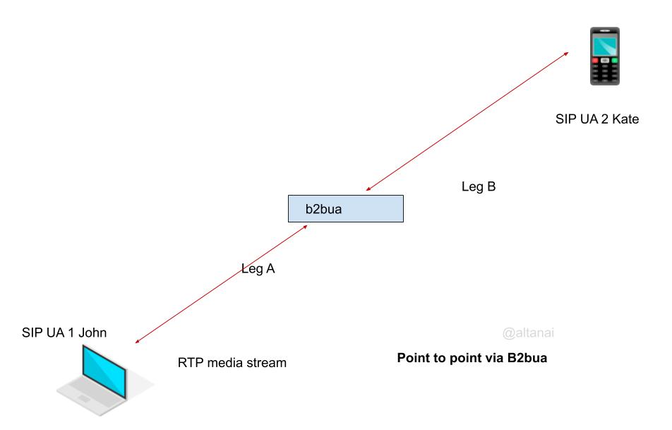
Back-To-Back RTP Session

Mostly like middlebox like translator but establishes separate legs RTP session with the endpoints, bridging the two sessions.

Takes complete responsibility of forwarding the correct RTP payload and maintain the relation between the SSRC and CNAMEs

Advantages of Back-To-Back RTP SessionDisadvantages of Back-To-Back RTP Session
(+) B2BUA / media bridge take responsibility tpo relay and manages congestion(-) It can be subjected to MIM attack or have a backdoor to eavesdrop on conversations

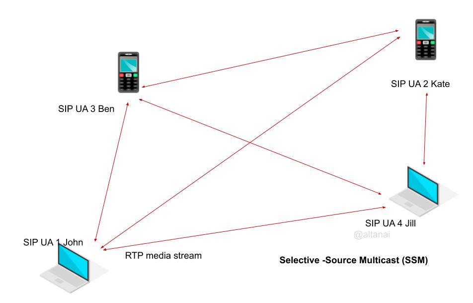
Point to Point using Multicast

Any-Source Multicast (ASM)

traffic from any particpant sent to the multicat group address reaches all other partcipants

Source-Specific Multicast (SSM)

Selective Sender stream to the multicast group which streams it to the recibers

Point to Multipoint using Mesh

many unicast RTP streams making a mesh

Point to Multipoint + Translator

Some more variants of this topology are Point to Multipoint with Mixer

Media Mixing Mixer

receives RTP streams from several endpoints and selects the stream(s) to be included in a media-domain mix. The selection can be through

static configuration or by dynamic, content-dependent means such as voice activation. The mixer then creates a single outgoing RTP stream from this mix.

Media Switching Mixer

RTP mixer based on media switching avoids the media decoding and encoding operations in the mixer, as it conceptually forwards the encoded media stream.

The Mixer can reduce bitrate or switch between sources like active speakers.

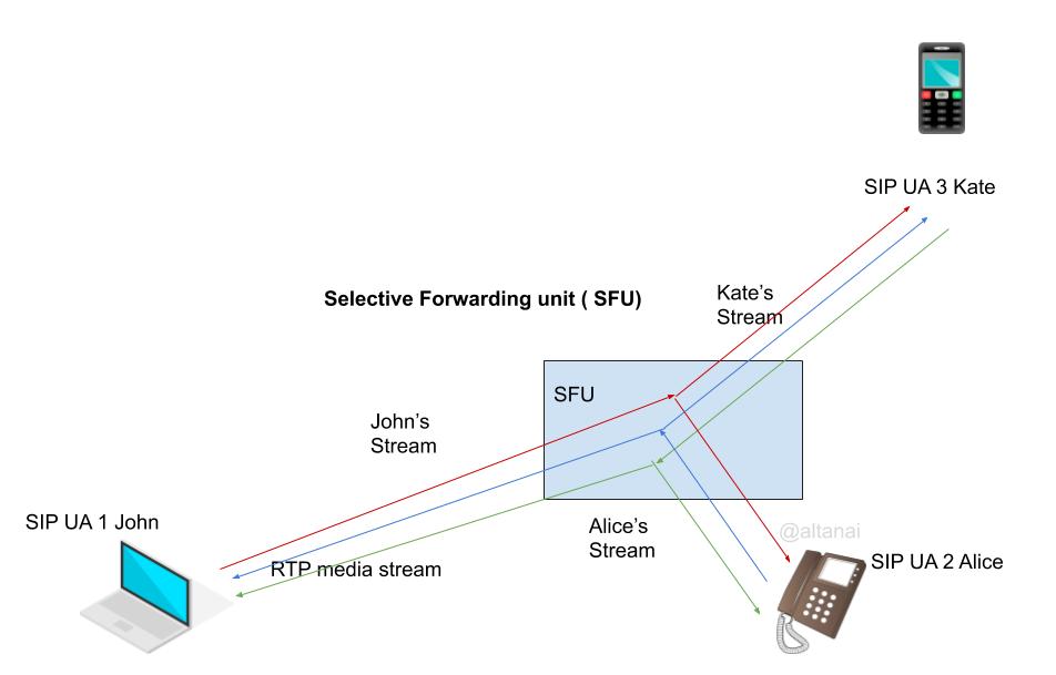
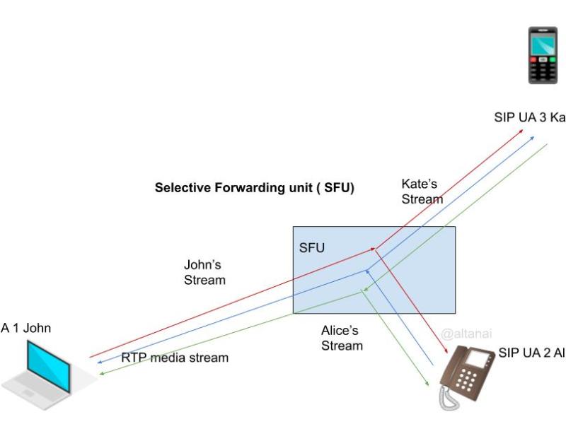
SFU ( Selective Forwarding Unit)

Middlebox can select which of the potential sources ( SSRC) transmitting media will be sent to each of the endpoints. This transmission is set up as an independent RTP Session.

Extensively used in videoconferencing topologies with scalable video coding as well as simulcasting.

Advantges of SFUDisadvatages of SFU
(+) Low lanetncy and low jitter buffer requirnment by avoiding re enconding
(+) saves on encoding decoding CPU utilization at server
(-) unable to manage network and control bitrate
(-) creates higher load on receiver when compared with MCU

On a high level, one can safely assume that given the current average internet bandwidth, for count of peers between 3-6 mesh architectures make sense however any number above it requires centralized media architecture.

Among the centralized media architectures, SFU makes sense for atmost 6-15 people in a conference however is the number of participants exceed that it may need to switch to MCU mode.

Simulcast

Encode in multiple variation and let SFU decide which endpoint should receive which stream type

Advantages of SFU +SimulcastDisadvantages of SFU +Simulcast
(+) Simulcast can ensure endpoints receive media stream depending on their requirnment/bandwidth/diaply(-) Uplink bandwidth reuirnment is high
(-) CPU intensive for sender for encoding many variations of outgoing stream

SVC ( scalable Video Coding)

Encodes in multiple layers based on various modalities such as

  • Signal to noise ration
  • temporal
  • Spatial
Advantages of SFU +SimulcastDisadvantages of SFU +Simulcast
(+) Simulcast can ensure endpoints receive media stream depending on their requirnment/bandwidth/diaply(-) Uplink bandwidth reuirnment is high
(-) CPU intensive for sender for encoding many variations of outgoing stream

Hybrid Topologies

There are various topologies for multi-endpoint conferences. Hybrid topologies include forward video while mixing audio or auto-switching between the configuration as load increases or decreases or by a paid premium of free plan

Hybrid model of forwarding and mixed streamings

Some endpoints receive forwarded streams while others receive mixed/composited streams.

Serverless models

Centralized topology in which one endpoint serves as an MCU or SFU.

Used by Jitsi and Skype

Point to Multipoint Using Video-Switching MCUs

Much like MCU but unlike MCU can switch the bitrate and resolution stream based on the active speaker, host or presenter, floor control like characteristics.

This setup can embed the characteristics of translator, selector and can even do congestion control based on RTCP

To handle a multipoint conference scenario it acts as a translator forwarding the selected RTP stream under its own SSRC, with the appropriate CSRC values and modifies the RTCP RRs it forwards between the domains

Cascaded SFUs

SFU chained reduces latency while also enabling scalability however takes a toll on server network as well as endpoint resources

Transport Protocols

Before getting into an in-depth discussion of all possible types of Media Architectures in VoIP systems, let us learn about TCP vs UDP.

TCP is a reliable connection-oriented protocol that sends REQ and receives ACK to establish a connection between communicating parties. It sequentially ends packets which can be resent individually when the receiver recognizes out of order packets. It is thus used for session creation due to its errors correction and congestion control features.

Once a session is established it automatically shifts to RTP over UDP. UDP even though not as reliable, not guarantying non-duplication and delivery error correction is used due to its tunnelling methods where packets of other protocols are encapsulated inside of UDP packet. However to provide E2E security other methods for Auth and encryption are used.

Audio PCAP storage and Privacy constraints for Media Servers

A Call session produces various traces for offtime monitoring and analysis which can include

CDR ( Call Detail Records ) – to , from numbers , ring time , answer time , duration etc

Signalling PCAPS – collected usually from SIP application server containing the SIP requests, SDP and responses. It shows the call flow sequences for example, who sent the INVITE and who send the BYE or CANCEL. How many times the call was updated or paused/resumed etc .

Media Stats – jitter , buffer , RTT , MOS for all legs and avg values

Audio PCAPS – this is the recording of the RTP stream and RTCP packets between the parties and requires explicit consent from the customer or user . The VoIP companies complying with GDPR cannot record Audio stream for calls and preserve for any purpose like audit , call quality debugging or an inspection by themselves.

Throwing more light on Audio PCAPS storage, assuming the user provides explicit permission to do so , here is the approach for carrying out the recording and storage operations.

Firther more , strict accesscontrol , encryption and annonymisation of the media packets is necessary to obfuscate details of the call session.

References :

To learn about the difference between Media Server tologies

  • centralized vs decentralised,
  • SFU vs MCU ,
  • multicast vs unicast ,

Read – SIP conferecning and Media Bridge

SIP conferencing and Media Bridges

SIP is the most popular signalling protocol in VOIP ecosystem. It is most suited to a caller-callee scenario , yet however supporting scalable conferences on VOIP is a market demand. It is desired that SIP must for multimedia stream but also provide conference control for building communication and collaboration apps for new and customisable solutions.

To read more about buildinga scalable VoIP Server Side architecture and

  • Clustering the Servers with common cache for High availiability and prompt failure recovery
  • Multitier archietcture ie seprartion between Data/session and Application Server /Engine layer
  • Micro service based architecture ie diff between proxies like Load balancer, SBC, Backend services , OSS/BSS etc
  • Containerization and Autoscalling

Read – VoIP/ OTT / Telecom Solution startup’s strategy for Building a scalable flexible SIP platform

VoIP/ OTT / Telecom Solution startup’s strategy for building a scalable flexible SIP platform

Scalable and Flexible platform. Let’s go in-depth to discuss how can one go about achieving scalability in SIP platforms. ulti geography Scaled via Universal Router, Cluster SIP telephony Server for High Availability, Multi-tier cluster architecture, Role Abstraction / Micro-Service based architecture, uted Event management and Event Driven architecture , Containerization, autoscaling , security , policies…

Audio and Acoustic Signal Processing

Audio signals are electronic representations of sound waves—longitudinal waves which travel through air, consisting of compressions and rarefactions and Audio Signal Processing focuses on the computational methods for intentionally altering auditory signals or sounds, in order to achieve a particular goal.

Application of audio Signal processing in general

  • storage
  • data compression
  • music information retrieval
  • speech processing ( emotion recognition/sentiment analysis , NLP)
  • localization
  • acoustic detection
  • Transmission / Broadcasting – enhance their fidelity or optimize for bandwidth or latency.
  • noise cancellation
  • acoustic fingerprinting
  • sound recognition ( speaker Identification , biometric speech verification , voice commands )
  • synthesis – electronic generation of audio signals. Speech synthesisers can generate human like speech.
  • enhancement (e.g. equalization, filtering, level compression, echo and reverb removal or addition, etc.)

Effects for audio streams processing

  • delay or echo
    To simulate reverberation effect, one or several delayed signals are added to the original signal. To be perceived as echo, the delay has to be of order 35 milliseconds or above.
    Implemented using tape delays or bucket-brigade devices.
  • flanger
    delayed signal is added to the original signal with a continuously variable delay (usually smaller than 10 ms).
    signal would fall out-of-phase with its partner, producing a phasing comb filter effect and then speed up until it was back in phase with the master
  • phaser
    signal is split, a portion is filtered with a variable all-pass filter to produce a phase-shift, and then the unfiltered and filtered signals are mixed to produce a comb filter.
  • chorus
    delayed version of the signal is added to the original signal. above 5 ms to be audible. Often, the delayed signals will be slightly pitch shifted to more realistically convey the effect of multiple voices.
  • equalization
    frequency response is adjusted using audio filter(s) to produce desired spectral characteristics. Frequency ranges can be emphasized or attenuated using low-pass, high-pass, band-pass or band-stop filters.
    overdrive effects such as the use of a fuzz box can be used to produce distorted sounds, such as for imitating robotic voices or to simulate distorted radiotelephone traffic
  • pitch shift
    shifts a signal up or down in pitch. For example, a signal may be shifted an octave up or down. This is usually applied to the entire signal, and not to each note separately. Blending the original signal with shifted duplicate(s) can create harmonies from one voice.
  • time stretching
    changing the speed of an audio signal without affecting its pitch.
  • resonators
    emphasize harmonic frequency content on specified frequencies. These may be created from parametric EQs or from delay-based comb-filters.
  • modulation
    change the frequency or amplitude of a carrier signal in relation to a predefined signal.
  • compression
    reduction of the dynamic range of a sound to avoid unintentional fluctuation in the dynamics. Level compression is not to be confused with audio data compression, where the amount of data is reduced without affecting the amplitude of the sound it represents.
  • 3D audio effects
    place sounds outside the stereo basis
  • reverse echo
    swelling effect created by reversing an audio signal and recording echo and/or delay while the signal runs in reverse.
  • wave field synthesis
    spatial audio rendering technique for the creation of virtual acoustic environments

ASP application in Telephony and mobile phones, by ITU (International Telegraph Union)

  • Acoustic echo control
    aims to eliminate the acoustic feedback, which is particularly problematic in the speakerphone use-case during bidirectional voice
  • Noise control
    microphone doesn’t only pick up the desired speech signal, but often also unwanted background noise. Noise control tries to minimize those unwanted signals . Multi-microphone AASP, has enabled the suppression of directional interferers.
  • Gain control
    how loud a speech signal should be when leaving a telephony transmitter as well as when it is being played back at the receiver. Implemented either statically during the handset design stage or automatically/adaptively during operation in real-time.
  • Linear filtering
    ITU defines an acceptable timbre range for optimum speech intelligibility. AASP in the form of linear filtering can help the handset manufacturer to meet these requirements.
  • Speech coding: from analog POTS based call to G.711 narrowband (approximately 300 Hz to 3.4 kHz) speech coder is a big leap in terms of call capacity. other speech coders with varying tradeoffs between compression ratio, speech quality, and computational complexity have been also made available. AASP provides higher quality wideband speech (approximately 150 Hz to 7 kHz).

ASP applications in music playback

AASP is used to provide audio post-processing and audio decoding capabilities for mobile media consumption needs, such as listening to music, watching videos, and gaming

  • Post-processing
    techniques as equalization and filtering allow the user to adjust the timbre of the audio such as bass boost and parametric equalization. Other techniques like adding reverberation, pitch shift, time stretching etc
  • Audio (de)coding: audio contianers like mp3 and AAC define how music is distributed, stored, and consumed also in Online music streaming services

ASP for virtual assitants

Virtual Assistance include a variety of servies from Apple’s Siri, Microsoft’s Cortana , Google’s Now , Alexa etc. ASP is used in

  • Speech enhancement
    multi-microphone speech pickup using beamforming and noise suppression to isolate the desired speech prior to forwarding it to the speech recognition engine.
  • Speech recognition (speech-to-text): this draws ideas from multiple disciplinary fields including linguistics, computer science, and AASP. Ongoing work in acoustic modeling is a major contribution to recognition accuracy improvement in speech recognition by AASP.
  • Speech synthesis (text-to-speech): this technology has come a very long way from its very robotic sounding introduction in the 1930s to making synthesized speech sound more and more natural.

Other areas of ASP

  • Virtual reality (VR) like VR headset / gaming simulators use three-dimensional soundfield acquisition and representation like Ambisonics (also known as B-format).

Ref :
wikipedia – https://en.wikipedia.org/wiki/Audio_signal_processing
IEEE – https://signalprocessingsociety.org/publications-resources/blog/audio-and-acoustic-signal-processing%E2%80%99s-major-impact-smartphones

RealTime Transport protocol (RTP) and supporting protocols


RTP is a protocol for delivering media stream end-to-end in real time over an IP network. Its applications include VoIP with SIP/XMPP, push to talk, WebRTC and teleconf, IOT media streaming, audio/video or simulation data, over multicast or unicast network services so on.

RTSP provides stream control features to an RTP stream along with session management.

RTCP is also a companion protocol to RTP, used for feedback and inter-frame synchronization.

  • Receiver Reports (RRs) include information about the packet loss, interarrival jitter, and a timestamp allowing computation of the round-trip time between the sender and receiver.
  • Sender Reports( SR) include the number of packets and bytes sent, and a pair of timestamps facilitating inter-stream synchronization.

SRTP provides security by end-to-end encryption while SDP provides session negotiation capabilities.

In this article I will be going over RTP and its associated protocols in depth to show the inner workings in a RTP media streaming session.

RTP (Real-time Transport Protocol)

RTP handles realtime multimedia transport between end to end network components . RFC 3550. RTP is extensible in headers format and simplified the application integration ( encryption , padding) and even use of proxies, mixers, translators etc.

Image result for RTP packet structure
Packet structure of RTP     
Image result for RTP header structure
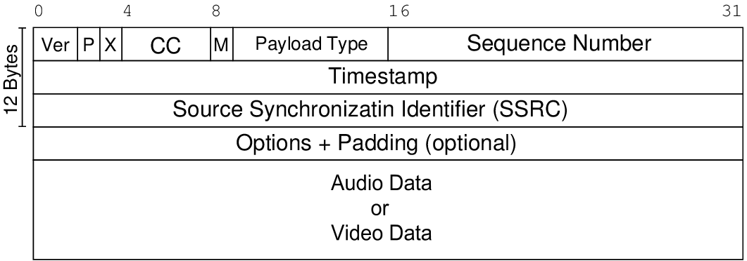
RTP Header contain timestamp , name of media source , codec type and sequence number .

RTP is independent of the underlying transport and network layers and can be described as an application layer protocol dealing with IP networks. While RTP was originally adapted from VAT( now obsolete) it was designed to be protocol independent ie it can be used with non-IP protocols like ATM, AAL5 as well as IP protocols IPV4, and IPv6. It does not address resource reservations and does not guarantee the quality of service for real-time services. However, it does provide services like payload type identification, sequence numbering, timestamping and delivery monitoring.

RTP Packet via Wireshark
RTP Packet Headers and position in packet

The sequence numbers included in RTP allow the receiver to reconstruct the sender’s packet sequence. Usage : Multimedia Multi particpant conferences, Storage of continuous data, Interactive distributed simulation, active badge, control and measurement applications.

RTP Session

Real-Time Transport Protocol
    [Stream setup by SDP (frame 554)]
        [Setup frame: 554]
        [Setup Method: SDP]
    10.. .... = Version: RFC 1889 Version (2)
    ..0. .... = Padding: False
    ...0 .... = Extension: False
    .... 0000 = Contributing source identifiers count: 0
    0... .... = Marker: False
    Payload type: ITU-T G.711 PCMU (0)
    Sequence number: 39644
    [Extended sequence number: 39644]
    Timestamp: 2256601824
    Synchronization Source identifier: 0x78006c62 (2013293666)
    Payload: 7efefefe7efefe7e7efefe7e7efefe7e7efefe7e7efefe7e...

Ordering via Timestamp (TS) and Sequence Number (SN)

  • TS ( Timestamp) used to order packets in correct timing order,
  • SN ( Sequence Number ) is used to detect packet loss

For a video frame that spans multiple packets – TS is same but SN is different.

Payload

RTP payload type is a 7-bit numeric identifier that identifies a payload format. 

Audio

  • 0 PCMU
  • 1 reserved (previously FS-1016 CELP)
  • 2 reserved (previously G721 or G726-32)
  • 3 GSM
  • 4 G723
  • 8 PCMA
  • 9 G722
  • 12 QCELP
  • 13 CN
  • 14 MPA
  • 15 G728
  • 18 G729
  • 19 reserved (previously CN)

Video

  • 25 CELB
  • 26 JPEG
  • 28 nv
  • 31 H261
  • 32 MPV
  • 33 MP2T
  • 34 H263
  • 72-76 reserved
  • 77–95 unassigned
  • dynamic H263-1998, H263-2000
  • dynamic (or profile) H264 AVC, H264 SVC , H265theora , iLBC , PCMA-WB ( G711 a law) , PCMU-WB ( G711 u law)G718, G719, G7221, vorbis , opus , speex , VP8 , VP9, raw , ac3 , eac3,

Note : difference between PCMA ( G711 alaw) and PCMU ( G711 u law)G.711 μ-law tends to give more resolution to higher range signals while G.711 A-law provides more quantization levels at lower signal levels.

Dynamic Payloads

Dynamic payload in RTP A/V Profile , unlike static ones above, are not assigned by IANA. They are assigned by means outside of the RTP profile or protocol specifications.

Tones

  • dynamic tone
  • telephone event ( DTMF)

These codes were initially specified in RFC 1890, “RTP Profile for Audio and Video Conferences with Minimal Control” (AVP profile), superseded by RFC 3550, and are registered as MIME types in RFC 3555.  Now registering static payload types is now considered a deprecated practice in favor of dynamic payload type negotiation.

Session identifiers

SSRC was designed for distinguishing several sources by labelling them differently. In an RTP session, each particpant maintains a full, separate space of SSRC identifiers. The set of participants included in one RTP session consists of those that can receive an SSRC identifier transmitted by any one of the participants either in RTP as the SSRC or a CSRC or in RTCP.

    0                   1                   2                   3
    0 1 2 3 4 5 6 7 8 9 0 1 2 3 4 5 6 7 8 9 0 1 2 3 4 5 6 7 8 9 0 1
   +-+-+-+-+-+-+-+-+-+-+-+-+-+-+-+-+-+-+-+-+-+-+-+-+-+-+-+-+-+-+-+-+
   |V=2|P|X|  CC   |M|     PT      |       sequence number         |
   +-+-+-+-+-+-+-+-+-+-+-+-+-+-+-+-+-+-+-+-+-+-+-+-+-+-+-+-+-+-+-+-+
   |                           timestamp                           |
   +-+-+-+-+-+-+-+-+-+-+-+-+-+-+-+-+-+-+-+-+-+-+-+-+-+-+-+-+-+-+-+-+
   |           synchronization source (SSRC) identifier            |
   +=+=+=+=+=+=+=+=+=+=+=+=+=+=+=+=+=+=+=+=+=+=+=+=+=+=+=+=+=+=+=+=+
   |            contributing source (CSRC) identifiers             |
   |                             ....                              |
   +-+-+-+-+-+-+-+-+-+-+-+-+-+-+-+-+-+-+-+-+-+-+-+-+-+-+-+-+-+-+-+-+

Synchronization source (SSRC) is a 32-bit numeric SSRC identifier for the source of a stream of RTP packets. This identifier is chosen randomly, with the intent that no two synchronization sources within the same RTP session will have the same SSRC identifier. All packets from a synchronisation source form part of the exact timing and sequence number space, so a receiver groups packets by synchronisation source for playback.  The binding of the SSRC identifiers is provided through RTCP. If a participant generates multiple streams in one RTP session, for example from separate video cameras, each MUST be identified as a different SSRC.

Contributing source (CSRC) – A source of a stream of RTP packets that has contributed to the combined stream produced by an RTP mixer. The mixer inserts a list of the SSRC identifiers of the sources, called CSRC list, that contributed to the generation of a particular packet into the RTP header of that packet. An example application is – audio conferencing where a mixer indicates all the talkers whose speech was combined to produce the outgoing packet, allowing the receiver to indicate the current talker, even though all the audio packets contain the same SSRC identifier (that of the mixer).

Timestamp calculation

Timesatmp is picked independantly from other streams in session. It is incemeneted based on packetization interval times the sampling rate. For example

  • audio 8000 Hz sampled at 20 ms, has blocks timestamps t1:160, t2:t1+160.. actual sampling may differ sligntly form this nominal rate.
  • video clock rate 90 kHz, frame rate 30 f/s would have blocks timestamps t1:3000 , t2:t1+3000.. For 25 fps t1:3600, t2:t1+3600. In some software coders timestamps can also be computer from the system clock such as gettimeofday()

Cross media synchronization using timestamp: RTP timestamp and NTP timestamps form a pair that identify the absolute time of a particular sample in the stream.

NTP timestamp in RTCP Sender Report SR
Numerical timestamp in RTP packet in the same session

UDP provides best-effort delivery of datagrams for point-to-point as well as for multicast communications.

Threading and Queues by RTP stacks

Reception and transmission queues handled are by the RTP stack.

Packet Reception – Application does not directly read packets from sockets but gets them from a reception queue. RTP stack is responsuble for updating this queue.

Packt transmission – Packets are not directly written to sockets but inserted in a transmission queue handled by the stack.

Incoming packet queue takes care of functions such as packet reordering or filtering out duplicate packets.

Threading model – Most libraries uses separate execution thread for each RTP session handling the queues.

RTSP (Real-Time Streaming Protocol)

RTSP is is Streaming Session protocol using RTP. It is also a network control protocol which uses TCP to maintain an end-to-end connection. Session protocols are actually negotiation/session establishment protocols that assist multimedia applications.

Applications : control real-time streaming media applications such as live audio and HD video streaming.
RTSP establishes a media session between RTSP end-points ( can be 2 RTSP media servers too) and initiates RTP streams to deliver the audio and video payload from the RTSP media servers to the clients.

Flow for RTSP stream between client and Server

  1. Initialize the RTP stack on Server and Client – Can be done by calling the constructor for object and ind initilaizing object with arguments

At Server

Server rtspserver = new Server();

At client

Client rtsplient = new Client();

2. Initiate TCP connection with the client and server respectively (via socket ) for the RTSP session

At Server

ServerSocket listenSocket = new ServerSocket(RTSPport);
rtspserver.RTSPsocket = listenSocket.accept();
rtspserver.ClientIPAddr = rtspserver.RTSPsocket.getInetAddress();

At Client

rtspclient.RTSPsocket = new Socket(ServerIPAddr, RTSP_server_port);

3. Set input and output stream filters

RTSPBufferedReader = new BufferedReader(new InputStreamReader(theServer.RTSPsocket.getInputStream()));
RTSPBufferedWriter = new BufferedWriter(new OutputStreamWriter(theServer.RTSPsocket.getOutputStream()));

4. Parse and Reply to RTSP commands

ReadLine from RTSPBufferedReader and parse tokens to get the RTSP request type

request = rtspserver.parse_RTSP_request();

On receiving each request send the appropriate response using RTSPBufferedWriter

rtspserver.send_RTSP_response();

Request Can be either of DESCRIBE, SETUP , PLAY, PAUSe , TEARDOWN

4. TEARDOWN RTSP Command

Either calls destructor which release the resources and end the session or call the BYE explicietly and close sockets

rtspserver.RTSPsocket.close();
rtspserver.RTPsocket.close();

RTP processing

  1. At Transmitter ( Server) – packetization of the video data into RTP packets.

This involves creating the packet, set the fields in the packet header, and copy the payload (i.e., one video frame) into the packet.

Get next frame to send from the video and build the RTP packet

RTPpacket rtp_packet = new RTPpacket(MJPEG_TYPE, imagenb, imagenb * FRAME_PERIOD, buf, video.getnextframe(buf));

RTP header formation from above accept parameters – PType, SequenceNumber, TimeStamp , buffer byte[] data and data_length of next frame in buffer go in the packet

3. TransmitterRetrieve the packet bitstream and store it in an array of bytes and send it as Datagram packet over UDP socket

senddp = new DatagramPacket(packet_bits, packet_length, ClientIPAddr, RTP_dest_port);
RTPsocket.send(senddp);

4. At Receiver – construct a new DatagramSocket to received RTP packets, on client’s RTP port

rcvdp = new DatagramPacket(buf, buf.length);
RTPsocket.receive(rcvdp);

5. Receiver RTP packet header and payload retrival

RTPpacket rtp_packet = new RTPpacket(rcvdp.getData(), rcvdp.getLength());
rtp_packet.getsequencenumber(); 
rtp_packet.getpayload(payload); // payload is bitstreams

6. Decode the payload as image/ video frame / audio segment and send for consumption by player or file or socket etc.

SRTP (Secure Real-time Transport Protocol)

Neither RTP or RTCP provide any flow encryption or authentication means, which is where SRTP comes into picture. SRTP is the security layer which resides between the RTP/RTCP application layer and the transport layer. It provides confidentiality, message authentication, and replay protection for both unicast and multicast RTP and RTCP streams.

SRTP Packet

Cryptographic context includes includes

  • session key used directly in encryption/message authentication
  • master key securely exchanged random bit string used to derive session keys
  • other working session parameters ( master key lifetime, master key identifier and length, FEC parameters, etc)
    it must be maintained by both the sender and receiver of these streams.

Salting keys” are used to protect against pre-computation and time-memory tradeoff attacks.

To learn more about SRTP specifically visit : https://telecom.altanai.com/2018/03/16/secure-communication-with-rtp-srtp-zrtp-and-dtls/

RTP in a VoIP Communication system and Conference streaming

Simulcast

Client encodes the same audio/video stream twice in different resolutions and bitrates and sending these to a router who then decides who receives which of the streams.

Multicast Audio Conference

Assume obtaining a multicast group address and pair of ports. One port is used for audio data, and the other is used for control (RTCP) packets. The audio conferencing application used by each conference participant sends audio data in small chunks of ms duration. Each chunk of audio data is preceded by an RTP header; RTP header and data are in turn contained in a UDP packet.

The RTP header indicates what type of audio encoding (such as PCM, ADPCM or LPC) is contained in each packet so that senders can change the encoding during a conference, for example, to accommodate a new participant that is connected through a low-bandwidth link or react to indications of network congestion.

Every packet networks, occasionally loses and reorders packets and delays them by variable amounts of time. Thus RTP header contains timing information and a sequence number that allow the receivers to reconstruct the timing produced by the source. The sequence number can also be used by the receiver to estimate how many packets are being lost.

For QoS, each instance of the audio application in the conference periodically multicasts a reception report plus the name of its user on the RTCP(control) port. The reception report indicates how well the current speaker is being received and may be used to control adaptive encodings. In addition to the user name, other identifying information may also be included subject to control bandwidth limits.

A site sends the RTCP BYE packet when it leaves the conference.

Audio and Video Conference

Audio and video media are transmitted as separate RTP sessions, separate RTP and RTCP packets are transmitted for each medium using two different UDP port pairs and/or multicast addresses. There is no direct coupling at the RTP level between the audio and video sessions, except that a user participating in both sessions should use the same distinguished (canonical) name in the RTCP packets for both so that the sessions can be associated.

Synchronized playback of a source’s audio and video is achieved using timing information carried in the RTCP packets

Layered Encodings

In conflicting bandwidth requirements of heterogeneous receivers, Multimedia applications should be able to adjust the transmission rate to match the capacity of the receiver or to adapt to network congestion.
Rate-adaptation should be done by a layered encoding with a layered transmission system.

In the context of RTP over IP multicast, the source can stripe the progressive layers of a hierarchically represented signal across multiple RTP sessions each carried on its own multicast group. Receivers can then adapt to network heterogeneity and control their reception bandwidth by joining only the appropriate subset of the multicast groups.

Mixers, Translators and Monitors

Note that in a VOIP system, where SIP is a signaling protocol , a SIP signalling proxy never participates in the media flow, thus it is media agnostic.

Mixer

An intermediate system that receives RTP packets from one or more sources, possibly changes the data format, combines the packets in some manner and then forwards a new RTP packet.

Example of Mixer for hi-speed to low-speed packet stream conversion . In conference cases where few participants are connected through a low-speed link where other have hi-speed link, instead of forcing lower-bandwidth, reduced-quality audio encoding for all, an RTP-level relay called a mixer may be placed near the low-bandwidth area.

This mixer resynchronises incoming audio packets to reconstruct the constant 20 ms spacing generated by the sender, mixes these reconstructed audio streams into a single stream, translates the audio encoding to a lower-bandwidth one and forwards the lower-bandwidth packet stream across the low-speed links.

All data packets originating from a mixer will be identified as having the mixer as their synchronization source.

RTP header includes a means for mixers to identify the sources that contributed to a mixed packet so that correct talker indication can be provided at the receivers.

Translator

An intermediate system that forwards RTP packets with their synchronization source identifier intact.

Examples of translators include devices that convert encodings without mixing, replicators from multicast to unicast, and application-level filters in firewalls.

Translator for Firewall Limiting IP packet pass

Some of the intended participants in the audio conference may be connected with high bandwidth links but might not be directly reachable via IP multicast, for reasons such as being behind an application-level firewall that will not let any IP packets pass. For these sites, mixing may not be necessary, in which case another type of RTP-level relay called a translator may be used.

Two translators are installed, one on either side of the firewall, with the outside one funneling all multicast packets received through asecure connection to the translator inside the firewall. The translator inside the firewall sends them again as multicast packets to a multicast group restricted to the site’s internal network.

Other cases :

video mixers can scales the images of individual people in separate video streams and composites them into one video stream to simulate a group scene.

Translator usage when connection of a group of hosts speaking only IP/UDP to a group of hosts that understand only ST-II, packet-by-packet encoding translation of video streams from individual sources without resynchronization or mixing.

Monitor

An application that receives RTCP packets sent by participants in an RTP session, in particular the reception reports, and estimates the current quality of service for distribution monitoring, fault diagnosis and long-term statistics.

Layered Encodings

In conflicting bandwidth requirements of heterogeneous receivers, Multimedia applications should be able to adjust the transmission rate to match the capacity of the receiver or to adapt to network congestion. Rate-adaptation should be done by a layered encoding with a layered transmission system.

In the context of RTP over IP multicast, the source can stripe the progressive layers of a hierarchically represented signal across multiple RTP sessions each carried on its own multicast group. Receivers can then adapt to network heterogeneity and control their reception bandwidth by joining only the appropriate subset of the multicast groups.

Multiplexing RTP Sessions

In RTP, multiplexing is provided by the destination transport address (network address and port number) which is different for each RTP session ( seprate for audio and video ). This helps in cases where there is chaneg in encodings , change of clockrates , detection of packet loss suffered and RTCP reporting .
Moreover RTP mixer would not be able to combine interleaved streams of incompatible media into one stream.

Interleaving packets with different RTP media types but using the same SSRC would introduce several problems. But multiplexing multiple related sources of the same medium in one RTP session using different SSRC values is the norm for multicast sessions.

REMB ( Receiver Estimated Maximum Bitrate)

RTCP message used to provide bandwidth estimation in order to avoid creating congestion in the network. Support for this message is negotiated in the Offer/Answer SDP Exchange. Contains total estimated available bitrate on the path to the receiving side of this RTP session (in mantissa + exponent format). REMB is used by

  • sender to configure the maximum bitrate of the video encoding.
  • notify the available bandwidth in the network and by media servers to limit the amount of bitrate the sender is allowed to send.

In Chrome it is deprecated in favor of the new sender side bandwidth estimation based on RTCP Transport Feedback messages.

Session Description Protocol (SDP) Capability Negotiation

SDP Offer/Answer flow

RTP can carry multiple formats.For each class of application (e.g., audio, video), RTP defines a profile and associated payload formats. Session Description Protocol used to specify the parameters for the sessions.

Usually in voIP systems SDP packets describing a session with codecs , open ports , media formats etc are embedded in a SIP request such as INVITE .

SDP can negotiate use of one out of several possible transport protocols. The offerer uses the expected least-common-denominator (plain RTP) as the actual configuration, and the alternative transport protocols as the potential configurations.

m=audio 53456 RTP/AVP 0 18
a=tcap:1 RTP/SAVPF RTP/SAVP RTP/AVPF

plain RTP (RTP/AVP)
Secure RTP (RTP/SAVP)
RTP with RTCP-based feedback (RTP/AVPF)
Real-time Transport Control Protocol (RTCP)-Based Feedback (RTP/SAVPF)

Adaptive bitrate control

Adapt the audio and video codec bitrates to the available bandwidth, and hence optimize audio & video quality. For video, since resolution is chosen at the start only , encoder use bitrate and frame-rate attributes only during runtime to adapt.

RTCP packet called TMMBR (Temporary Maximum Media Stream Bit Rate Request) is sent to the remote client.


References:

SIP conferencing and Media Bridges


SIP is the most popular signalling protocol in VOIP ecosystem. It is most suited to a caller-callee scenario, yet however supporting scalable conferences on VOIP is a market demand. It is desired that SIP must for multimedia stream but also provide conference control for building communication and collaboration apps for new and customisable solutions.

SIP Recap

Apart from VoIP, it is used in other multimedia technologies like online games, video conferencing, instant messaging and other services. SIP is an IETF-defined signalling protocol for controlling communication sessions over IP. It is an application layer protocol, which runs on TCP, UDP and SCTP. SIP is based on the Web protocol Hypertext Transfer Protocol (HTTP) and is a request/response protocol.

SIPv1 :SIPv1 was text-based. It used Session Description Protocol (SDP) to describe the sessions and UDP as a transport protocol. SIPv1 only handled session establishment and did not handle Mid-conference controls.

SIPv2 :Simple Conference Invitation Protocol( SCIP) utilized Transmission Control Protocol (TCP) as the transport protocol to manage conferences. Ur was based on HTTP and used e-mail addresses as identifiers for users. SIP v2 was also text-based but based on HTTP and could use both UDP and TCP as transport protocols. The combination of SIPv1 and SCIP resulted in Session Initiation Protocol. 

SIP is used to distribute session descriptions among potential participants. Once the session description is distributed, SIP can be used to negotiate and modify the parameters of the session and terminate the session. Role of SIP in conference involves

  • initiating confs
  • inviting participants
  • enabling them to join conf
  • leave conf
  • terminate conf
  • expel participants
  • configure media flow
  • control activities in conf

Mesh vs star topology

Mesh has p2p streaming thus has maximum data privacy and low cost for service provider because tehre arnt any media stream to take care of. Infact it just comes out of the box with WebRTC peerconnections. But ofcourse you cant scale a p2p mesh based archietcture . Although the communication provider is now indifferent to the media stream traffic , the call quality of session is entirely dependent of the end clients processing and their bandwidths which in my experince cannot accomodate more than 20-25 particpants in a call even above average bandwidth of 30-40 Mbps uplink , downlink both.
On the other hand in a star topolgy the participants only need to communicate with the media server , irrrespective of the network conditions of the receivers .

Centralised (star) structure

In a Centralised ( star) signalling model , all communication flows via a centralised control point

Applications of star topology couold be MCU and SFU.

Centralised Media / MCU

Centralised Media / MCU

Multipoint Control Unit (MCU) uses mixer found in video conferencing bridges.

  • (+) proven interworking with legacy systems
  • (+) singel point to manage transcoding
  • (+) energy efficient mode of operation , keeping cleint side stream management low
  • (+) single point for DTMF inband/signalling processing
  • (-) CPU and resource intensive on server side
  • (-) adds latency for traversal via media server
  • (-) self managed scaling , heavy tarffic and resource maantaince
  • (-) possible security vulnerability as server decryptes media packets

Centralised Media via SFU

SFU + simulcast

Single Forwarding Unit ( SFU) is a neew topology where the centralzed media server only forwards or proxies the streams without mixing.

  • (+) scales for low latency video streaming
  • (+) less CPU consumption of server
  • (+) can control output stream for each peers based on their network capabilities
  • (-) still susceptab;e to security vulnearability at the focal point.

Decentralised structure

In a decentralised ( mesh) signalling structure, participants can communicate p2p

Decentralised media, Multi unicast streaming

Decentralised media, Multicast streaming

Mesh based communication

Limitations of WebRTC mesh Architecture

WebRTC is intrinsically a p2p system and as more participants join the session , the network begins to resemble a mesh. Audio and textual data being the lighter option from heavy video media streams can still adjust to the difficult conditions without much noticible lag. However video streams take a hit when peers are on difficult bandwidth and use differnt qualities of video sources.

Lets assume 3 different clients communication on WebRTC mesh session

  1. WebRTC browser on high resolution system ( desktop , laptop , kiosk) – this client will likely have high quality stream and would like to consume high quality as well
  2. Mobile browser of native WebRTC client – this will have aberage quality stream and may fluctuate owing to telecom network handover or instability in moving beween locations
  3. Embedded system like Raspberry pi with camera module – since this is an embedded system likley part of IoT survillance system , it will try to restrict the outgoing usuage and incoming stream consumption to minimal.

Some issue with WebRTC mesh conference include

  • Unmatched quality of stream for idnividual p2p streams in mesh make it difficult to have a homogenous session quality.
  • Often video packet go out of sync with audio packets leading to delay or freezing due to packet loss.
  • Pixelating video when resolution of incoming video does not match the viewers display mode eg : low quality 320×280 pixel video viewed on desktop monitor with 1080×720 resolution.
  • Different source encoders at peers WebRTC client behave different . eg : webrtc stream from an embedded system like Rpi will be different from that of a WebRTC browser like Safari or mozilla or a mobile browser like chrome on Android.

Although with auto adjustments in WebRTC’s media stack , combinations of bitrate and resolution are manipulated in realtime based on feedback packets to adjust the qualities of your video streaming to bandwidth constraints of your own and the peer, there exist many difficulties to have large number of partcipants ( in order of few tens to hundreds) to join the mesh session. Even with an excellent connection and great scale of bandwidth of 5G networks it is just not feasible to host even upto 100 users on a common mesh based video system.

Unicast, BroastCast and Multicast media distribution

UnicastBroadCastMultiCast
one-to-one transmissionone-to-all within a range

Its types are
– limited broadcast and
– Direct broadcast
one-to-many

servers direct single streams towards any listener who wants to connect. the stream is replicated many times accross the network.
usage : RTC over the networks between two specific endpointsusage : conference streamingusage : IPTV that distributes to hundres or thousands of viewers

Inspite of both being a star topology, SFU/Selective Forwarding Unit is different from MCU as in contrast to MCU it does not do any heavy duty processing on media streams , it only fetches the stream and routes them to other peers .

On the other hand MCU ( Multipoint Control Unit ) media servers need a lot of computational strength to perform many operations on RTP stream such as mixing , multiplexing, filytering echo /noise etc.

Scalable Video Coding (SVC) for large groups

while simulcast streams multiple versions of the same stream with differenet qualities like resolutions where the SFU can pick the appropriate one for the destination. SFU can also forward different framerates to differnrt detsinations absed on their bandwidth. Some of the Conference Bridge types :-

1. Bridge

Centralised entity to book conf , start conf , leave conf . Therefore single point of failure potentially .

  • To create conf : conf created on a bridge URL , bridge registers on SIP Server, participants join the conf on the bridge using INVITES
  • To stop conf : either participant can Leave with BYE or conf can terminate by sending BYE to all

2. Endpoints as Mixer

Endpoints handle stream , decentralised media , therefore adhoc suited

(-) mixer UAs cannot leave untill conf finishes

3. Mesh

complex and more processing power on each UA required

  • (+) no single point of failure
  • (-) high network congestion and endpoint processing
  • (-) endpoints have to handle NATIng

Large scale multiparticipant WebRTC sessions

A MCU ( Media control Unit) which acts as a bridge between all particpants is a tradiotionally used system to host large conferences. However a MCU limits or lowers the bandwidth usuage by packing the streams together .A SFU ( Single Forwarding Unit ) on the other hand simply forwards the stream.

This setup is usualy designed with heavy bandwidth and upload rates in mind and are more scalable and resilient to bad quality stream than p2p type mesh setups. As these media gateways servers scale to accomodate more simultanous real time users , their bandwidth consumption is heavy and expensive( some thing to be kept in mind while buying instances fro cloud providers like azure or AWS).

Some of the many options to make SFU (single forwarding unit setup) for WebRTC mediastreams are listed below :-

Kurento

Opensource (Apache 2.0) WebRTC gateways that has buildin integration to OpenCV.

Pipeline Architecture Design Pattern

Features in KMS ( Kurento Media Server) include Augmentation, face reciognition, filetrs, Object tracking and even virtual fencing.

Other features like mixing , transcoding, recording as well as client APIs make it suitable for integration into rich multimedia applications.

  • (+) It can function as both MCU and SFU.
  • (+) Added Media processing and transformations – Augmented Relaity , Blending , Mixing , Analyzing ..
  • (+) ML freindly + openCV filter ( samples provided )
  • (+) pipeline used with computer vision

Nightly build, good docuemntion and developer gtraction make this a good choice. Latest version at the time of writing this article is Kurento 6.15.0 release on november 2020.

Licode

Opensource (MIT) WebRTC Comm platform by Lynckia.

Simple and starightforward to build from source . Latest release is v8 on sep 2019.

Erizo, its WebRTC core, is by default is SFU but also can be switched to MCU for more features like output streaming, transcoding.

It is written in c++ and uses nodejs API to communicate with server.

Supports modules like recording which can be added.

Jitsi

Opensource (Aapache 2.0)Video conferencing called Jitsi Video Bridge ( jvb).

JITSI Components

  • Jitsi VideoBridge – SFU
  • Jicofo – “Focus” component that initiates Jingle on behalf of JVB
  • Jigasi – SIP to XMPP signaling and media gateway
  • Jirecon – Component that allows for recording of RTP streams
  • Jibri – New live recording component

Other client side components and SDK

  • lib-jitsi-meet/Strophe.js – Javascript (Browser/Node.js)
  • XMPPFramework/MeetRTC_iOS – iOS
  • Smack – Java/Android
Jits conferencing ( SFU)
  • (+) Supports high capacity SFU. Provides tools ( jibri) for recording and/or streaming.
  • (+) Has Android and iOS SDKs.
  • (-) Low sip support ( more on XMPP) Orignally uses XMPP signalling but can communicate with SIP platfroms using a gateway which is part of Jitsi project .

It is best used as a binary package on debina / ubuntu instead of self Maven compile. The most recent release is 2.0.5390 release on 12 Jan 2021.

MediaSoup

Opensource ( ISC) SFU conferecing server for both WebRTc and plain non secured RTP.

Producer consumer archietecture design pattern.

  • (+) It is signalling agnostic
  • (+) nodejs module in server ( media handling in cpp)
  • (+) Provides JS and c++ client libraries
  • (+) audio/video consumers or consumers can be Gstreamer and FFMPEG scripts

Relatively new with less documentation however simpleistic and minimilistic deisgn make it easy to grasp and run.

Janus

WebRTc gateway is also opensource ( GNU GPL v3)

Build on C. It does have ability to switch between SFU and MCU and provides pligins on top like recording.

By default uses a Websocket based protocol , HTTP/JSON and XMPP but can communicate with SIP platforms too using plugin.

Asterisk SFU

MCU based pure SIP signalling and media server ( GNU GPL v2 ) from Sangoma Technologies.

Powerful server core to many OTT / VOIP providers and call centre platfroms.

  • (+) Can be modified to any role using combination of hundres of modules.
  • (-) Project does not provide client SDK.

Red5

live streaming with SDK for native (ios , android) and html5. cutom server side application.

  • (+) supports Ip camera , drone , RTSP, RTMP , hardware encoders ( many client instances )
  • (+) failover to HLS and flash

JANUS as WebRTC SFU

This article is to introduce Janus based SFU media architecture for WebRTC systems. It also aims at evaluating the performance of the VP9 simulcast p2p model with Janus based SFU system.


Janus

We know Janus is a popular small footprint gateway/media Server with support for WebRTC features like JSEP/SDP, ICE, DTLS-SRTP, DataChannels. Its plugins expose Janus API over different transports – HTTP, WS, rabbitMQ, Unix sockets, MQTT so on. Other plugins provide deeper modifications such as Video SFU, Audio MCU, SIP/RTSP gateways, broadcasting etc.

Centralised media conferencing / mixing service using Janus

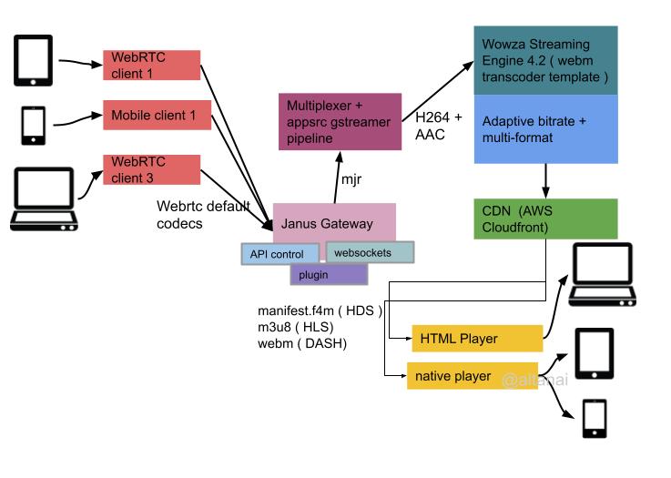
Streaming Video via CDN

Tip : use mixing for Audio and Relay for video in large participant sessions.

Server Selection and Setup from source

Janus Setup on public ec2 isntance. Since the a media server can clog the server space make sure to choose alarge instance like c5.large. Sample log file size

Install prerequisite libraries

sudo apt-get install libmicrohttpd-dev libjansson-dev libnice-dev libssl-dev libsrtp-dev libsofia-sip-ua-dev libglib2.0-dev libopus-dev libogg-dev libini-config-dev libcollection-dev libwebsockets-dev pkg-config gengetopt automake libtool doxygen graphviz git libconfig-dev cmake

Make Sure libsrtp v2.x is installed instead of existing 1.4 in debain /ubuntu default such as

libsrtp0-dev is already the newest version (1.4.5~20130609~dfsg-2ubuntu1).

Manually installing libsrtp2 from https://github.com/cisco/libsrtp

wget https://github.com/cisco/libsrtp/archive/v2.2.0.tar.gz
tar xfv v2.2.0.tar.gz
cd libsrtp-2.2.0
./configure --prefix=/usr --enable-openssl
make shared_library && sudo make install

Since we are going to use websocket as signalling, ensure lws (libwebsocket) >= 2.0.0 is installed

git clone https://libwebsockets.org/repo/libwebsockets
cd libwebsockets
mkdir build
cd build
cmake -DLWS_MAX_SMP=1 -DLWS_WITHOUT_EXTENSIONS=0 -DCMAKE_INSTALL_PREFIX:PATH=/usr -DCMAKE_C_FLAGS="-fpic" 
make && sudo make install

Also libnice (at least v0.1.16) need to be installed

Get Janus source code and configure

git clone git://github.com/meetecho/janus-gateway.git
cd janus-gateway
sh autogen.sh
./configure 
--disable-data-channels 
--disable-docs 
--prefix=/opt/janus LDFLAGS="-L/usr/local/lib -Wl,-rpath=/usr/local/lib" CFLAGS="-I/usr/local/include"

At this point Janus prinst a config detail such as below and asks if its ok . Ensure Websocket is yes. One can start the make process if it is

Compiler:                  gcc
libsrtp version:           2.x
SSL/crypto library:        OpenSSL
DTLS set-timeout:          not available
Mutex implementation:      GMutex (native futex on Linux)
DataChannels support:      no
Recordings post-processor: no
TURN REST API client:      no
Doxygen documentation:     no
Transports:
    REST (HTTP/HTTPS):     yes
    WebSockets:            yes
    RabbitMQ:              no
    MQTT:                  no
    Unix Sockets:          yes
    Nanomsg:               no
Plugins:
    Echo Test:             yes
    Streaming:             yes
    Video Call:            yes
    SIP Gateway:           yes
    NoSIP (RTP Bridge):    yes
    Audio Bridge:          yes
    Video Room:            yes
    Voice Mail:            yes
    Record&Play:           yes
    Text Room:             yes
    Lua Interpreter:       no
    Duktape Interpreter:   no
Event handlers:
    Sample event handler:  no
    WebSocket ev. handler: yes
    RabbitMQ event handler:no
    MQTT event handler:    no
    Nanomsg event handler: no
    GELF event handler:    yes
External loggers:
    JSON file logger:      no
JavaScript modules:        no

Make and install

make && sudo make install

Making configs

sudo make configs

For details refer to actual README on Janus git repo https://github.com/meetecho/janus-gateway

Start

By default, Janus starts in foreground, as a console application that stop with Ctrl + c command

./janus

Starting janus as backvroudn or daemon service

sudo ./janus -N -d 0 --daemon --log-file /var/log/janus

tailing the log file

> tail -f /var/log/janus
---------------------------------------------------
  Starting Meetecho Janus (WebRTC Server) v0.11.1
---------------------------------------------------

Checking command line arguments...
Debug/log level is 0
Debug/log timestamps are disabled
Debug/log colors are enabled

references : https://janus.conf.meetecho.com/docs/service.html

Issues with installation of janus

Before resolving any issue, it is important to verify whether you are runing multiple versions of janus on your system

altanai@xx:~/janus-gateway$ janus --version
Janus commit: bed081c03ad4854f3956898646198100a8ed82cf
Compiled on:  Fri Apr  2 07:28:14 UTC 2021

janus 0.11.1

altanai@xx:~/janus-gateway$ ./janus --version
Janus commit: c970528037d46d52a4bc1fd7db2a44c900c2baf2
Compiled on:  Thu Apr  8 18:01:36 UTC 2021

janus 0.10.8

If this is so, delete the one you dont require. I’d go with rmeoove the one installed globally.

Cmake version error

If you see an error in rabbitmq instalation , which is part of janus installation

CMake 3.12...3.18 or higher is required.  You are running version 3.10.2

then proceed to remove existing version and install updates ne by first removing tghe existing cmake version

sudo apt remove cmake
wget https://github.com/Kitware/CMake/releases/download/v3.20.1/cmake-3.20.1-linux-x86_64.sh
sh cmake-3.20.1-linux-x86_64.sh

check version

>> cmake-3.20.1-linux-x86_64/bin/cmake --version
cmake version 3.20.1

lib websocket error in libjanus_websockets.so

Couldn't load transport plugin 'libjanus_websockets.so': /opt/janus/lib/janus/transports/libjanus_websockets.so: undefined symbol: lws_hdr_custom_length

Libwebsockets (LWS) is a flexible, lightweight pure C library for implementing modern network protocols easily with a tiny footprint, using a nonblocking event loop.

Fisrt check the version of libwebsockets u have on ur machine . If it is lesse that 2.0.0 version

>> apt show libwebsockets-dev

Package: libwebsockets-dev
Version: 2.0.3-3build1
Priority: optional
Section: universe/libdevel
Source: libwebsockets
Origin: Ubuntu
Maintainer: Ubuntu Developers <ubuntu-devel-discuss@lists.ubuntu.com>
Original-Maintainer: Laszlo Boszormenyi (GCS) <gcs@debian.org>
Bugs: https://bugs.launchpad.net/ubuntu/+filebug
Installed-Size: 502 kB
Depends: libwebsockets8 (= 2.0.3-3build1), libev-dev, libssl-dev, libuv1-dev, zlib1g-dev
Homepage: https://libwebsockets.org/
Download-Size: 133 kB
APT-Manual-Installed: yes
APT-Sources: http://us-west-1.ec2.archive.ubuntu.com/ubuntu bionic/universe amd64 Packages
Description: lightweight C websockets library - development files
 Libwebsockets is a lightweight pure C library for both websockets
 clients and servers built to use minimal CPU and memory resources
 and provide fast throughput in both directions.
 .
 This package contains the header files needed for developing programs
 using libwebsockets and a static library.

Follow the steps to install libwebsocket ,  libwebsockets >= 2.0.0, the current v3.2-stable is good http://libwebsockets.org/

Failures due to ICE

ICE failed for component 1 in stream 1… 
No WebRTC media anymore
 WebRTC resources freed;

Self Signed SSL certs

Make a new directory for SSL certs

mkdir /home/ubuntu/ssl

generate certs 

openssl req -new -newkey rsa:4096 -nodes -keyout key.pem -out cert.csr
openssl x509 -req -sha256 -days 365 -in cert.csr -signkey key.pem -out cert.pem
chmod 600 cert.csr
chmod 600 cert.pem
chmod 600 key.pem

Remember to allow advanced access if the ssl are self signed and not from a varified CA

Update janus config

Path for Janus configuration is usually /opt/janus/etc/janus/janus.jcfg as given by the prefix during instalation. some of the types of config are

>> vi /opt/janus/etc/janus/janus.jcfg
general: {
   configs_folder = "/opt/janus/etc/janus" # Configuration files folder
   plugins_folder = "/opt/janus/lib/janus/plugins" # Plugins folder
   transports_folder = "/opt/janus/lib/janus/transports" # Transports folder
   events_folder = "/opt/janus/lib/janus/events" # Event handlers folder
   loggers_folder = "/opt/janus/lib/janus/loggers" # External loggers folder
....
}
  • SSL certs for DTLS can also be specified under certificates
  • Restricting media ports between a range . Comes in handy when u have to selectively open ports ona cloud instance such as AWS instance
media: {
        ipv6 = false
        #min_nack_queue = 500
        rtp_port_range = "20000-40000"
        #dtls_mtu = 1200
        #no_media_timer = 1
        #slowlink_threshold = 4
        #twcc_period = 100
        #dtls_timeout = 500
....
}
  • changing NAT for STUN/TURN servers to gather ICE

using 1:1 NAT( suited to Amzon EC2) requires specifying public address

nat_1_1_mapping = "1.1.1.1"
  • To change transport http , set http to true from false

goto installation location for janus config

cd /opt/janus/etc/janus/
> vi /opt/janus/etc/janus/janus.transport.http.jcfg

general: {
    #events = true                 # Whether to notify event handlers about transport events (default=true)
    json = "indented"              # Whether the JSON messages should be indented (default),
                                   # plain (no indentation) or compact (no indentation and no spaces)
    base_path = "/janus"           # Base path to bind to in the web server (plain HTTP only)
    http = true                    # Whether to enable the plain HTTP interface
    port = 8088                    # Web server HTTP port
    #interface = "eth0"            # Whether we should bind this server to a specific interface onlya
    #ip = "x.x.x.x"                # Whether we should bind this server to a specific IP address (v4 or v6) only
    https = true                   # Whether to enable HTTPS (default=false)
    secure_port = 8089             # Web server HTTPS port, if enabled
    #secure_interface = "eth0"     # Whether we should bind this server to a specific interface only
    #secure_ip = "192.168.0.1"     # Whether we should bind this server to a specific IP address (v4 or v6) only
    #acl = "127.,192.168.0."       # Only allow requests coming from this comma separated list of addresses
}

Change path for certs and key pem files

> vi janus.jcfg

certificates: {
        cert_pem = "/home/ubuntu/ssl/cert.pem"
        cert_key = "/home/ubutu/ssl/key.pem"
        #cert_pwd = "secretpassphrase"
        #dtls_accept_selfsigned = false
        #dtls_ciphers = "your-desired-openssl-ciphers"
        #rsa_private_key = false
      #ciphers = "PFS:-VERS-TLS1.0:-VERS-TLS1.1:-3DES-CBC:-ARCFOUR-128"
}

There are options for other ciphers and passphrass , leave them for now.

  • To change transport ws for websocket
general: {
        #events = true            # Whether to notify event handlers about transport events (default=true)
        json = "indented"         # Whether the JSON messages should be indented (default),
                                  # plain (no indentation) or compact (no indentation and no spaces)
        #pingpong_trigger = 30    # After how many seconds of idle, a PING should be sent
        #pingpong_timeout = 10    # After how many seconds of not getting a PONG, a timeout should be detected

        ws = true                 # Whether to enable the WebSockets API
        ws_port = 8188            # WebSockets server port
        #ws_interface = "eth0"    # Whether we should bind this server to a specific interface only
        #ws_ip = "192.168.0.1"    # Whether we should bind this server to a specific IP address only
        wss = true                # Whether to enable secure WebSockets
        wss_port = 8989           # WebSockets server secure port, if enabled
        #wss_interface = "eth0"   # Whether we should bind this server to a specific interface only
        #wss_ip = "192.168.0.1"   # Whether we should bind this server to a specific IP address only
        #ws_logging = "err,warn"  # libwebsockets debugging level as a comma separated list of things
                                  # to debug, supported values: err, warn, notice, info, debug, parser,
                                  # header, ext, client, latency, user, count (plus 'none' and 'all')
        #ws_acl = "127.,192.168.0." # Only allow requests coming from this comma separated list of addresses
}

Simillar to http transport conf above , also update the certs section with valid path for ssl certs

Check Janus Running

Running ports check ( http )

> sudo lsof -i  | grep janus
janus     26450          ubuntu    7u  IPv6 418550      0t0  UDP *:rfe 
janus     26450          ubuntu    8u  IPv6 418551      0t0  UDP *:5004 
janus     26450          ubuntu   17u  IPv6 418557      0t0  TCP *:omniorb (LISTEN)
janus     26450          ubuntu   20u  IPv6 672518      0t0  TCP *:8089 (LISTEN)
janus     26450          ubuntu   24u  IPv4 672519      0t0  TCP *:8188 (LISTEN)
janus     26450          ubuntu   25u  IPv4 672520      0t0  TCP *:8989 (LISTEN) 

Janus INFO

Going to deployed janus URL like http://x.x.x.x:8088/janus/info

   "janus": "server_info",
   "transaction": "rGuo8HNI4wu",
   "name": "Janus WebRTC Gateway",
   "version": 26,
   "version_string": "0.2.6",
   "author": "Meetecho s.r.l.",
   "commit-hash": "not-a-git-repo",
   "compile-time": "Wed Feb 28 07:02:15 UTC 2018",
   "log-to-stdout": true,
   "log-to-file": false,
   "data_channels": false,
   "session-timeout": 60,
   "server-name": "MyJanusInstance",
   "local-ip": "x.x.x.x",
   "ipv6": false,
   "ice-lite": false,
   "ice-tcp": false,
   "api_secret": false,
   "auth_token": false,
   "event_handlers": false,
   "transports": {
      "janus.transport.http": {
         "name": "JANUS REST (HTTP/HTTPS) transport plugin",
         "author": "Meetecho s.r.l.",
         "description": "This transport plugin adds REST (HTTP/HTTPS) support to the Janus API via libmicrohttpd.",
         "version_string": "0.0.2",
         "version": 2
      },
      "janus.transport.websockets": {
         "name": "JANUS WebSockets transport plugin",
         "author": "Meetecho s.r.l.",
         "description": "This transport plugin adds WebSockets support to the Janus API via libwebsockets.",
         "version_string": "0.0.1",
         "version": 1
      }
   },
   "events": {},
   "plugins": {
      "janus.plugin.voicemail": {
         "name": "JANUS VoiceMail plugin",
         "author": "Meetecho s.r.l.",
         "description": "This is a plugin implementing a very simple VoiceMail service for Janus, recording Opus streams.",
         "version_string": "0.0.6",
         "version": 6
      },
      "janus.plugin.audiobridge": {
         "name": "JANUS AudioBridge plugin",
         "author": "Meetecho s.r.l.",
         "description": "This is a plugin implementing an audio conference bridge for Janus, mixing Opus streams.",
         "version_string": "0.0.10",
         "version": 10
      },
      "janus.plugin.echotest": {
         "name": "JANUS EchoTest plugin",
         "author": "Meetecho s.r.l.",
         "description": "This is a trivial EchoTest plugin for Janus, just used to showcase the plugin interface.",
         "version_string": "0.0.7",
         "version": 7
      },
      "janus.plugin.recordplay": {
         "name": "JANUS Record&amp;Play plugin",
         "author": "Meetecho s.r.l.",
         "description": "This is a trivial Record&amp;Play plugin for Janus, to record WebRTC sessions and replay them.",
         "version_string": "0.0.4",
         "version": 4
      },
      "janus.plugin.textroom": {
         "name": "JANUS TextRoom plugin",
         "author": "Meetecho s.r.l.",
         "description": "This is a plugin implementing a text-only room for Janus, using DataChannels.",
         "version_string": "0.0.2",
         "version": 2
      },
      "janus.plugin.videoroom": {
         "name": "JANUS VideoRoom plugin",
         "author": "Meetecho s.r.l.",
         "description": "This is a plugin implementing a videoconferencing SFU (Selective Forwarding Unit) for Janus, that is an audio/video router.",
         "version_string": "0.0.9",
         "version": 9
      },
      "janus.plugin.sipre": {
         "name": "JANUS SIPre plugin",
         "author": "Meetecho s.r.l.",
         "description": "This is a simple SIP plugin for Janus (based on libre instead of Sofia), allowing WebRTC peers to register at a SIP server and call SIP user agents through the gateway.",
         "version_string": "0.0.1",
         "version": 1
      },
      "janus.plugin.videocall": {
         "name": "JANUS VideoCall plugin",
         "author": "Meetecho s.r.l.",
         "description": "This is a simple video call plugin for Janus, allowing two WebRTC peers to call each other through the gateway.",
         "version_string": "0.0.6",
         "version": 6
      },
      "janus.plugin.streaming": {
         "name": "JANUS Streaming plugin",
         "author": "Meetecho s.r.l.",
         "description": "This is a streaming plugin for Janus, allowing WebRTC peers to watch/listen to pre-recorded files or media generated by gstreamer.",
         "version_string": "0.0.8",
         "version": 8
      },
      "janus.plugin.nosip": {
         "name": "JANUS NoSIP plugin",
         "author": "Meetecho s.r.l.",
         "description": "This is a simple RTP bridging plugin that leaves signalling details (e.g., SIP) up to the application.",
         "version_string": "0.0.1",
         "version": 1
      },
      "janus.plugin.sip": {
         "name": "JANUS SIP plugin",
         "author": "Meetecho s.r.l.",
         "description": "This is a simple SIP plugin for Janus, allowing WebRTC peers to register at a SIP server and call SIP user agents through the gateway.",
         "version_string": "0.0.7",
         "version": 7
      }
   }
}

ECHO Test

An Echo test is part of Janus and can be done via reached via deployed server url https://x.x.x.x:8084/echotest.html

For a valid SDP message notice the contact headers in chrome://webrtc-internals

Local Description (mungled)

O line represents origin

type: offer, sdp: v=0
o=- 1331622865522329207 2 IN IP4 127.0.0.1


Audio Media stream in m line 

m=audio 9 UDP/TLS/RTP/SAVPF 111 103 104 9 0 8 106 105 13 110 112 113 126
c=IN IP4 0.0.0.0

Video media stream in m line 

m=video 9 UDP/TLS/RTP/SAVPF 96 97 98 99 100 101 102 122 127 121 125 107 108 109 124 120 123
c=IN IP4 0.0.0.0


Data

m=application 9 UDP/DTLS/SCTP webrtc-datachannel
c=IN IP4 0.0.0.0

Remote Description

Origin Line

type: answer, sdp: v=0
o=- 6397148042001786590 2 IN IP4 54.193.51.199

Audio Stream

m=audio 9 UDP/TLS/RTP/SAVPF 111 9 0 8 106 105 13 110 112 113
c=IN IP4 54.193.51.199

Video Stream

m=video 9 UDP/TLS/RTP/SAVPF 96 98 100 102 127 125 108 97 99 101 122 121 107 109
c=IN IP4 54.193.51.199

Data 

m=application 0 UDP/DTLS/SCTP 0
c=IN IP4 54.193.51.199

VideoCall – https://x.x.x.x:8084/videocalltest.html

Run

./opt/janus/bin/janus

Plugin (above ) and then procceeds to join the room ( screenshot below)

After this Janus procced to do JSEP offer / answer signalling with ICE checks and then does keepalive checks for the duraion of the session .

Stream Types

Unicast

a=sendonly
a=recvonly
a=sendrecv
a=inactive

Simulcast

https://x.x.x.x:8084/videocalltest.html?simulcast=true

LD Libbary Path Exception

If you see an missing encryption exception , start janus with LD_LIBRARY_PATH

export LD_LIBRARY_PATH=/usr/lib && /opt/janus/bin/janus --debug-level=7 --stun-server=stun.l.google.com:19302 --event-handlers --full-trickle

ICE resolution in Runtime

Trickle ICE Command Line params give console output as

[janus.cfg]
    general: {
        debug_level: 7
    }
    certificates: {
    }
    nat: {
        stun_server: stun.l.google.com
        stun_port: 19302
        full_trickle: true
    }
    media: {
    }
    transports: {
    }
    plugins: {
    }
    events: {
        broadcast: yes
    }
    loggers: {
    }

With NAT 1:1 mapping

export LD_LIBRARY_PATH=/usr/lib && /opt/janus/bin/janus --debug-level=7 --nat-1-1=54.193.51.199 --stun-server=stun.l.google.com:19302 --rtp-port-range=20000-50000 

1 to 1 NAT mpapping coordinates with amazon ec2

[janus.cfg]
    general: {
        debug_level: 7
    }
    certificates: {
    }
    nat: {
        nat_1_1_mapping: 54.193.51.199
    }
    media: {
        rtp_port_range: 20000-50000
    }
    transports: {
    }
    plugins: {
    }
    events: {
    }
    loggers: {
    }

WebRTC Client for Janus System

Test client

Using the html sample clients

cd html
admin.html            citeus.html      e2etest.html   index.html      nosiptest.html          siptest.html        textroomtest.html   voicemailtest.html audiobridgetest.html  demos.html       echotest.html  multiopus.html  recordplaytest.html     streamingtest.html  videocalltest.html  vp9svctest.html canvas.html           devicetest.html  footer.html    navbar.html     screensharingtest.html  support.html        videoroomtest.html

check lsb release and then Install Nodejs to host client page

>> lsb_release -a
curl -sL https://deb.nodesource.com/setup_15.x | sudo -E bash -
sudo apt-get install -y nodejs

Http WebServer

npm init
npm install http-server
node_modules/http-server/bin/http-server

To be able to compile native addons from npm you’ll need to install the development tools:

sudo apt install build-essential

open the client in webrtc supported browser at http://x.x.x.x:8080/videoroomtest.html

If you see a issues

 No WebRTC media anymore; 0x7fbe20001a40 0x7fbe20002440
 WebRTC resources freed; 0x7fbe20001a40 0x7fbe20001320
 Handle and related resources freed; 0x7fbe20001a40 0x7fbe20001320

Then it is likley a NAT issues and you should look at jcfg config file to see whether the interface is specified corectly

# Generic settings
interface = "x.x.x.x"                                     # Interface to use (will be used in SDP)
server_name = "WebrtcMCUJanus"                                  # Public name of this Janus instance

Security consideration before taking janus live

Hide the dependencies

hide_dependencies = true  

By default, a call to the “info” endpoint of either the Janus or Admin API now als returns the versions of the main dependencies (e.g., libnice, libsrtp, which crypto library is in use and so on). Should you want that info not to be disclose, set ‘hide_dependencies’ to true.

Common spam attack. source https://groups.google.com/g/meetecho-janus/c/IcJd3e4V1F8

Issues : Janus is throwing an error Invalid url /ws/v1/cluster/apps/new-application

Possible solution : changing port of http transport

References


To read more about Media Archietctures and topologies such as point-point , point-to-multipoint , multicast , translators, mixers and SFU goto :

Media Architecture, RTP topologies

With the sudden onset of Covid-19 and building trend of working-from-home , the demand for building scalable conferncing solution and virtual meeting room has skyrocketed . Here is my advice if you are building a auto- scalable conferencing solution

To read more on the topologies of conferencing systems ( Mesh vs Star , Unicast vs Multicast and SVC) read :

SIP conferencing and Media Bridges

SIP is the most popular signalling protocol in VOIP ecosystem. It is most suited to a caller-callee scenario , yet however supporting scalable conferences on VOIP is a market demand. It is desired that SIP must for multimedia stream but also provide conference control for building communication and collaboration apps for new and customisable solutions.

crtmpserver + ffmpeg

This post will show the process of installing , running and using crtmpserver on ubuntu 64 bit machine with gstreamer .

gcc and cmake

We shall build gstreamer directly from sources . For this we first need to determine if gcc is installed on the machine .

If not installed then  run the following command

GNU Compiler Collection (GCC) is a compiler system produced by the GNU Project supporting various programming languages( C, C++, Objective-C, Fortran, Java, Ada, Go etc).

sudo apt-get install build-essential

once it is isnatlled it can be tested with printing the version

Screenshot from 2016-06-09 11-24-33.png

cmake is a software compilation tool.It uses compiler independent configuration files, and generate native makefiles and workspaces that can be used in the differemt compiler environment .

Crtmpserver

To get the source code from git install git first . Then clone the project from https://github.com/j0sh/crtmpserver

sudo apt-get git
git clone https://github.com/j0sh/crtmpserver.git
cd crtmpserver/builders/cmake

Next we create all makefile’s using cmake .

cmake .

Output should look as follows

Screenshot from 2016-06-09 11-47-05

Run make to do compilation

make

Screenshot from 2016-06-09 11-57-19

Run using following command . If should print out a list of ports and their respecting functions

./crtmpserver/crtmpserver crtmpserver/crtmpserver.lua

+—————————————————————————–+
| Services|
+—+—————+—–+————————-+————————-+
| c | ip | port| protocol stack name | application name |
+—+—————+—–+————————-+————————-+
|tcp| 0.0.0.0| 1112| inboundJsonCli| admin|
+—+—————+—–+————————-+————————-+
|tcp| 0.0.0.0| 1935| inboundRtmp| appselector|
+—+—————+—–+————————-+————————-+
|tcp| 0.0.0.0| 8081| inboundRtmps| appselector|
+—+—————+—–+————————-+————————-+
|tcp| 0.0.0.0| 8080| inboundRtmpt| appselector|
+—+—————+—–+————————-+————————-+
|tcp| 0.0.0.0| 6666| inboundLiveFlv| flvplayback|
+—+—————+—–+————————-+————————-+
|tcp| 0.0.0.0| 9999| inboundTcpTs| flvplayback|
+—+—————+—–+————————-+————————-+
|tcp| 0.0.0.0| 6665| inboundLiveFlv| proxypublish|
+—+—————+—–+————————-+————————-+
|tcp| 0.0.0.0| 8989| httpEchoProtocol| samplefactory|
+—+—————+—–+————————-+————————-+
|tcp| 0.0.0.0| 8988| echoProtocol| samplefactory|
+—+—————+—–+————————-+————————-+
|tcp| 0.0.0.0| 1111| inboundHttpXmlVariant| vptests|
+—+—————+—–+————————-+————————-+

If you the following types of errors while pushing a stream to crtmpserver , they just denote they your pipe is not using the correct format.

/home/altanai/crtmpserver/sources/thelib/src/netio/epoll/tcpacceptor.cpp:154 Client connected: 127.0.0.1:55524 -&amp;amp;amp;amp;amp;amp;amp;amp;amp;gt; 0.0.0.0:8080
/home/altanai/crtmpserver/sources/thelib/src/netio/epoll/iohandlermanager.cpp:119 Handlers count changed: 11-&amp;amp;amp;amp;amp;amp;amp;amp;amp;gt;12 IOHT_TCP_CARRIER
/home/altanai/crtmpserver/sources/thelib/src/protocols/http/basehttpprotocol.cpp:281 Headers section too long
/home/altanai/crtmpserver/sources/thelib/src/protocols/http/basehttpprotocol.cpp:153 Unable to read response headers: CTCP(16) &amp;amp;amp;amp;amp;amp;amp;amp;amp;lt;-&amp;amp;amp;amp;amp;amp;amp;amp;amp;gt; TCP(13) &amp;amp;amp;amp;amp;amp;amp;amp;amp;lt;-&amp;amp;amp;amp;amp;amp;amp;amp;amp;gt; [IHTT(14)] &amp;amp;amp;amp;amp;amp;amp;amp;amp;lt;-&amp;amp;amp;amp;amp;amp;amp;amp;amp;gt; IH4R(15)
/home/altanai/crtmpserver/sources/thelib/src/netio/epoll/tcpcarrier.cpp:89 Unable to signal data available
/home/altanai/crtmpserver/sources/thelib/src/netio/epoll/iohandlermanager.cpp:129 Handlers count changed: 12-&amp;amp;amp;amp;amp;amp;amp;amp;amp;gt;11 IOHT_TCP_CARRIER
/home/altanai/crtmpserver/sources/thelib/src/protocols/protocolmanager.cpp:45 Enqueue for delete for protocol [IH4R(15)]
/home/altanai/crtmpserver/sources/thelib/src/application/baseclientapplication.cpp:240 Protocol [IH4R(15)] unregistered from application: appselector
/home/altanai/crtmpserver/sources/thelib/src/netio/epoll/tcpacceptor.cpp:154 Client connected: 127.0.0.1:44964 -&amp;amp;amp;amp;amp;amp;amp;amp;amp;gt; 0.0.0.0:9999
/home/altanai/crtmpserver/sources/thelib/src/netio/epoll/iohandlermanager.cpp:119 Handlers count changed: 11-&amp;amp;amp;amp;amp;amp;amp;amp;amp;gt;12 IOHT_TCP_CARRIER
/home/altanai/crtmpserver/sources/thelib/src/protocols/ts/inboundtsprotocol.cpp:211 I give up. I'm unable to detect the ts chunk size
/home/altanai/crtmpserver/sources/thelib/src/protocols/ts/inboundtsprotocol.cpp:136 Unable to determine chunk size
/home/altanai/crtmpserver/sources/thelib/src/netio/epoll/tcpcarrier.cpp:89 Unable to signal data available
/home/altanai/crtmpserver/sources/thelib/src/netio/epoll/iohandlermanager.cpp:129 Handlers count changed: 12-&amp;amp;amp;amp;amp;amp;amp;amp;amp;gt;11 IOHT_TCP_CARRIER
/home/altanai/crtmpserver/sources/thelib/src/protocols/protocolmanager.cpp:45 Enqueue for delete for protocol [ITS(17)]
/home/altanai/crtmpserver/sources/thelib/src/application/baseclientapplication.cpp:240 Protocol [ITS(17)] unregistered from application: flvplayback
/home/altanai/crtmpserver/sources/thelib/src/netio/epoll/tcpacceptor.cpp:154 Client connected: 127.0.0.1:37754 -&amp;amp;amp;amp;amp;amp;amp;amp;amp;gt; 0.0.0.0:1935
/home/altanai/crtmpserver/sources/thelib/src/netio/epoll/iohandlermanager.cpp:119 Handlers count changed: 11-&amp;amp;amp;amp;amp;amp;amp;amp;amp;gt;12 IOHT_TCP_CARRIER
/home/altanai/crtmpserver/sources/thelib/src/protocols/rtmp/inboundrtmpprotocol.cpp:77 Handshake type not implemented: 85
/home/altanai/crtmpserver/sources/thelib/src/protocols/rtmp/basertmpprotocol.cpp:309 Unable to perform handshake
/home/altanai/crtmpserver/sources/thelib/src/netio/epoll/tcpcarrier.cpp:89 Unable to signal data available
/home/altanai/crtmpserver/sources/thelib/src/netio/epoll/iohandlermanager.cpp:129 Handlers count changed: 12-&amp;amp;amp;amp;amp;amp;amp;amp;amp;gt;11 IOHT_TCP_CARRIER
/home/altanai/crtmpserver/sources/thelib/src/protocols/protocolmanager.cpp:45 Enqueue for delete for protocol [IR(19)]
/home/altanai/crtmpserver/sources/thelib/src/application/baseclientapplication.cpp:240 Protocol [IR(19)] unregistered from application: appselector
/home/altanai/crtmpserver/sources/thelib/src/netio/epoll/tcpacceptor.cpp:154 Client connected: 127.0.0.1:48368 -&amp;amp;amp;amp;amp;amp;amp;amp;amp;gt; 0.0.0.0:6666
/home/altanai/crtmpserver/sources/thelib/src/protocols/liveflv/inboundliveflvprotocol.cpp:51 _waitForMetadata: 1
/home/altanai/crtmpserver/sources/thelib/src/netio/epoll/iohandlermanager.cpp:119 Handlers count changed: 11-&amp;amp;amp;amp;amp;amp;amp;amp;amp;gt;12 IOHT_TCP_CARRIER
/home/altanai/crtmpserver/sources/thelib/src/protocols/liveflv/baseliveflvappprotocolhandler.cpp:45 protocol CTCP(16) &amp;amp;amp;amp;amp;amp;amp;amp;amp;lt;-&amp;amp;amp;amp;amp;amp;amp;amp;amp;gt; TCP(20) &amp;amp;amp;amp;amp;amp;amp;amp;amp;lt;-&amp;amp;amp;amp;amp;amp;amp;amp;amp;gt; [ILFL(21)] registered to app flvplayback
/home/altanai/crtmpserver/sources/thelib/src/protocols/liveflv/inboundliveflvprotocol.cpp:102 Frame too large: 6324058
/home/altanai/crtmpserver/sources/thelib/src/netio/epoll/tcpcarrier.cpp:89 Unable to signal data available
/home/altanai/crtmpserver/sources/thelib/src/netio/epoll/iohandlermanager.cpp:129 Handlers count changed: 12-&amp;amp;amp;amp;amp;amp;amp;amp;amp;gt;11 IOHT_TCP_CARRIER
/home/altanai/crtmpserver/sources/thelib/src/protocols/protocolmanager.cpp:45 Enqueue for delete for protocol [ILFL(21)]
/home/altanai/crtmpserver/sources/thelib/src/protocols/liveflv/baseliveflvappprotocolhandler.cpp:58 protocol [ILFL(21)] unregistered from app flvplayback

ffmpeg

Download and install ffmpeg from git

 git clone https://git.ffmpeg.org/ffmpeg.git ffmpeg
cd ffmpeg

Once the source code is obtained we need to configure , make and make install it .
We need to have following plugins for muxing and ecoding like libx264 for h264parse , so we configure with the following options

./configure \
  --prefix=&amp;amp;amp;amp;amp;quot;$HOME/ffmpeg_build&amp;amp;amp;amp;amp;quot; \
  --pkg-config-flags=&amp;amp;amp;amp;amp;quot;--static&amp;amp;amp;amp;amp;quot; \
  --extra-cflags=&amp;amp;amp;amp;amp;quot;-I$HOME/ffmpeg_build/include&amp;amp;amp;amp;amp;quot; \
  --extra-ldflags=&amp;amp;amp;amp;amp;quot;-L$HOME/ffmpeg_build/lib&amp;amp;amp;amp;amp;quot; \
  --bindir=&amp;amp;amp;amp;amp;quot;$HOME/bin&amp;amp;amp;amp;amp;quot; \
  --enable-gpl \
  --enable-libass \
  --enable-libfreetype \
  --enable-libopus \
  --enable-libtheora \
  --enable-libvorbis \
  --enable-libx264 \
  --enable-libx265 \
  --enable-nonfree

the make and make install

make
sudo make install

Screenshot from 2016-06-09 16-59-49

Incase of errors  on ffmpeg configure command , you need to install the respective missing / not found library

libass

sudo apt-get install libass-dev

lamemp3

sudo apt-get install libmp3lame-dev

libaacplus

sudo apt-get install autoconf
sudo apt-get install libtool

wget -O libaacplus-2.0.2.tar.gz http://tipok.org.ua/downloads/media/aacplus/libaacplus/libaacplus-2.0.2.tar.gz
tar -xzf libaacplus-2.0.2.tar.gz
cd libaacplus-2.0.2
./autogen.sh --with-parameter-expansion-string-replace-capable-shell=/bin/bash --host=arm-unknown-linux-gnueabi --enable-static

make
sudo make install

libvorbis
compressed audio format for mid to high quality (8kHz-48.0kHz, 16+ bit, polyphonic) audio and music at fixed and variable bitrates from 16 to 128 kbps/channe. It is from the same reank as MPEG4 AAC

wget http://downloads.xiph.org/releases/vorbis/libvorbis-1.3.2.tar.bz2
tar -zxvf libvorbis-1.3.2.tar.bz2
cd libvorbis-1.3.2
./configure &amp;amp;amp;amp;&amp;amp;amp;amp; make &amp;amp;amp;amp;&amp;amp;amp;amp; make install

libx264
encoding video streams into the H.264/MPEG-4 AVC compression format, and is released under the terms of the GNU GPL.

git clone git://git.videolan.org/x264
cd x264
./configure --host=arm-unknown-linux-gnueabi --enable-static --disable-opencl
make
sudo make install

libvpx
libvpx is an emerging open video compression library which is gaining popularity for distributing high definition video content on the internet.

sudo apt-get install checkinstall
git clone https://chromium.googlesource.com/webm/libvpx
cd libvpx
./configure
make
sudo checkinstall --pkgname=libvpx --pkgversion=&quot;1:$(date +%Y%m%d%H%M)-git&quot; --backup=no     --deldoc=yes --fstrans=no --default

librtmp
librtmp provides support for the RTMP content streaming protocol developed by Adobe and commonly used to distribute content to flash video players on the web.

sudo apt-get install libssl-dev
cd /home/pi/src
git clone git://git.ffmpeg.org/rtmpdump
cd rtmpdump
make SYS=posix
sudo checkinstall --pkgname=rtmpdump --pkgversion=&quot;2:$(date +%Y%m%d%H%M)-git&quot; --backup=no --deldoc=yes --fstrans=no --default

Reference:
http://www.videolan.org/developers/x265.html
https://trac.ffmpeg.org/wiki/CompilationGuide/RaspberryPi
http://wiki.serviio.org/doku.php?id=howto:linux:install:raspbian
http://lame.sourceforge.net/

Additionally “pkg-config –list-all” command list down all the installed libraries.


RTMP streaming

1.start the stream from linux machine using ffmpeg

ffmpeg -f video4linux2 -s 320x240 -i /dev/video0 -f flv -s qvga -b 750000 -ar 11025 -metadata streamName=aaa "tcp://<hidden_ip>:6666/live";

Screenshot from 2016-06-11 17-50-02

2.view the incoming packets and stats on terminal at crtmpserver

Screenshot from 2016-06-11 17-53-22

3.playback the livestream from another machine

using ffplay
ffplay -i rtmp://server_ip:1935/live/ccc

Screenshot from 2016-06-09 15-43-58

RTSP streaming

1.start the rtsp stream from linux machine using ffmpeg

here using resolution 320×240 and stream name test

ffmpeg -f video4linux2 -s 320x240 -i /dev/video0 -an -r 10 -c:v libx264 -q 1 -f rtsp -metadata title=test rtsp://server_ip:5554/flvplayback

crtmp2

2.view the incoming packets and stats on terminal at crtmpserver

3.playback the livestream from another machine using

ffplay

ffplay rtsp://server_ip:5554/flvplayback/test

Screenshot from 2016-06-09 18-17-07

VLC

vlc rtsp://server_ip:5554/flvplayback/test


GStreamer-1.8.1 rtsp server and client on ubuntu

GStreamer is a streaming media framework, based on graphs of filters which operate on media data.

Gstreamer is constructed using a pipes and filter architecture.
The basic structure of a stream pipeline is that you start with a stream source (camera, screengrab, file etc) and end with a stream sink (screen window, file, network etc). The ! are called pads and they connect the filters.

Data that flows through pads is described by caps (short for capabilities). Caps can be though of as mime-type (e.g. audio/x-raw, video/x-raw) along with mime-type (e.g. width, height, depth).

Source Code

Download the latest archives from https://gstreamer.freedesktop.org/src/

Source code on git : https://github.com/GStreamer

Primarily 3 files are required

  1. gstreamer-1.8.1.tar.xz
  2. gst-plugins-base-1.8.1.tar.xz
  3. gst-rtsp-server-1.8.1.tar.xz

If the destination machine is a ec2 instance one can also scp the tar.xz file there

To extract the tar.xz files use tar -xf <filename> it will create a folder for each package.

Prerequisites

build-essentials

sudo apt-get install build-essentials

bison

flex

GLib >= 2.40.0

GLib package contains low-level libraries useful for providing data structure handling for C, portability wrappers and interfaces for such runtime functionality as an event loop, threads, dynamic loading and an object system.

sudo apt-get install libglib2.0-dev

gstreamer

Installing gstreamer 1.8.1 . Gstreamer create a media stream with elements and properties as will be shown on  later sections of this tutorial .

cd gstreamer-1.8.1
./configure
make
sudo make install

Screenshot from 2016-05-19 16-51-29.png

Screenshot from 2016-05-19 16-55-27.png

Screenshot from 2016-05-19 16-56-05.png

after installation  export the path

export LD_LIBRARY_PATH=/usr/local/lib

then verify the installation of the gstreamer by

gst-inspect-1.0

provides information on installed gstreamer modules ie print out a long list ( about 123 in my case ) plugin that are installed such as coreelements:

capsfilter: CapsFilter ximagesink: ximagesink: Video sink videorate: videorate: Video rate adjuster typefindfunctions: image/x-quicktime: qif, qtif, qti typefindfunctions: video/quicktime: mov, mp4 typefindfunctions: application/x-3gp: 3gp typefindfunctions: audio/x-m4a: m4a typefindfunctions: video/x-nuv: nuv typefindfunctions: video/x-h265: h265, x265, 265 typefindfunctions: video/x-h264: h264, x264, 264 typefindfunctions: video/x-h263: h263, 263 typefindfunctions: video/mpeg4: m4v typefindfunctions: video/mpeg-elementary: mpv, mpeg, mpg typefindfunctions: application/ogg: ogg, oga, ogv, ogm, ogx, spx, anx, axa, axv typefindfunctions: video/mpegts: ts, mts typefindfunctions: video/mpeg-sys: mpe, mpeg, mpg typefindfunctions: audio/x-gsm: gsm

gst plugins

Now build the plugins

cd gst-plugins-base-1.8.1
./configure
make
sudo make install


gst plugins good

cd gst-plugins-good-1.8.1.tar
./configure
 make
sudo make install

RTSP Server

Now make and install the rtsp server

cd gst-rtsp-server-1.8.1
./configure

last few lines from console traces

Configuration
Version : 1.8.1
Source code location : .
Prefix : /usr/local
Compiler : gcc -std=gnu99
CGroups example : no

make

It will compile the examples .

sudo make install


stream video test src

~/mediaServer/gst-rtsp-server-1.8.1/examples]$./test-launch --gst-debug=0 &quot;( videotestsrc ! video/x-raw,format=(yuv),width=352,height=288,framerate=15/1 ! x264enc ! rtph264pay name=pay0 pt=96 )&quot;
stream ready at rtsp://127.0.0.1:8554/test

Ref:

Manual for developers : https://gstreamer.freedesktop.org/data/doc/gstreamer/head/gst-rtsp-server/html/index.html


Simplest pipeline

gst-launch-1.0 fakesrc ! fakesink

➜ ~ gst-launch-1.0 fakesrc ! fakesink Setting pipeline to PAUSED ... Pipeline is PREROLLING ... Pipeline is PREROLLED ... Setting pipeline to PLAYING ... New clock: GstSystemClock
To stop press ctrl +c ^
Chandling interrupt. Interrupt: Stopping pipeline ... Execution ended after 0:00:48.004547887 Setting pipeline to PAUSED ... Setting pipeline to READY ... Setting pipeline to NULL ... Freeing pipeline ... [/sourcecode ] or to display to a audiovideosink gst-launch-1.0 videotestsrc ! autovideosink
Screenshot from 2016-05-20 12-31-18.png To capture webcam
gst-launch v4l2src ! xvimagesink

Screenshot from 2016-05-20 13-06-56.png

Wowza RTMP Authentication with Third party Token provider over Tiny Encryption Algorithm (TEA)

this article is focused on  Wowza RTMP Authentication with  Third party Token provider over Tiny Encryption Algorithm (TEA)  and  is a continuation of the previous post about setting up a basic RTMP Authentication module on Wowza Engine above version 4.

The task is divided into 3 parts .

  1. RTMP Encoder Application
  2. Wowza RTMP Auth module
  3. Third party Authentication Server

The component diagram is as follows :

Copy of Publisher App iOS

The detailed explanation of the components are :

1.Wowza RTMP Auth module

The Wowza Server receives a rtmp stream url in the format as :

rtmp://username:pass@wowzaip:1935/Application/stteamname

It considers the username and pass to be user credentials . RTMP auth Module invokes the getPassword() function inside of deployed application class  passing the username as parameter.  The username is then  encrypted using TEA ( Tiny Encryption algorithm)

TEA is a block cipher  which is based on symmetric ( private) key encryption . Input is a 64 bit of plain or cipher text with a 128 bit key resulting in output of cipher or plain text respectively.

The code for encryption  is


TEA.encrypt( username, sharedSecret );

The code to make a connection to third party auth server is


 url = new URL(serverTokenValidatorURL);
 
 URLConnection connection;
 connection = url.openConnection();
 connection.setDoOutput(true);

OutputStreamWriter out = new OutputStreamWriter(connection.getOutputStream());
 out.write("clientid=" + TEA.encrypt( username, sharedSecret ););
 out.close(); 

The sharedsecret is the common key which is with both the Auth server and wowza server . It must be atleast a 16 digit alphanumeric / special character based key . An example of shared secret is abcdefghijklmnop .The value can be stored as property in Application.xml file.

<Property>
<Name>secureTokenSharedSecret</Name>
<Value><![CDATA[abcdefghijklmnop]]></Value>
</Property>

<Property>
<Name>serverTokenValidatorURL</Name>
<Value>http://127.0.0.1:8080/TokenProvider/authentication/token</Value&gt;
</Property>

The values of serverTokenValidatorURL is the third party auth server listening for REST POST request .

The code for receiving the incoming  resulting json data is


	ObjectMapper mapper = new ObjectMapper();
	JsonNode node = mapper.readTree(connection.getInputStream()); 
	node = node.get("publisherToken") ;
	String token = node.asText();
        String token2 =TEA.decrypt(token, sharedSecret);

2.Third party Authentication Server

The 3rd party Auth server stores the passwords for users or performs oauth based authentication . It uses a shared secret key to decrypt the token based on TEA as explained in above section .

The code to decrypt the incoming clientId


TEA.decrypt(id, sharedSecret);

Add own custom logic to check files , databases etc for obtaining the password corresponding to the username as decrypted above.

The code to encrypt the password for the user if exists or send invalid response if non exists is


        try {

            String clientID = TEA.decrypt(id, sharedSecret);
            
            String token= findUserPassword(clientID);
            
             token = TEA.encrypt(token, sharedSecret); 
                        
            return "{\"publisherToken\":\""  + token+ "\"}";
            
        }catch (Exception ex) {

            return "{\"error\":\"Invalid Client\"}";
        }

The final callflow thus becomes :

Copy of Publisher App iOS (1)

Screenshots :

Screenshot_2015-09-16-20-22-37Screenshot_2015-09-17-18-36-23Screenshot_2015-09-16-20-22-42Screenshot_2015-09-16-20-23-30

Wowza RTMP Authenticate Module

To purpose of the article is the use the RTMP Authentication Module in wowza Engine .  This will enable us to intercept a connect request with username and password to be checked from any outside source like – database , password file , third party token provider , third party oauth etc.  Once the password provided by user is verified with the authentic password form external sources the user is allowed to connect and publish.

Step 1 : Create a new Wowza Media Server Project in Eclipse .  It is assumed that user has already integrated WowzaIDE into eclipse .

File -> New -> Wowza Media Server Project  

Step 2: Give any project name . I named it as “RTMPAuthSampleCode”.

wowza RTMP Auth
wowza RTMP Auth

Step 3 :   Point the location to existing Wowza Engine installed in local environment .

It is usually in /usr/local/WowzaStreamingEngine/

Wowza RTMP Auth
Wowza RTMP Auth

Step 4 : Proceed with the creation , uncheck the event methods as we are not using them right now .

Screenshot from 2015-09-17 13:10:24

Step 5: Put the code in class.

The class RTMPAuthSampleCode extends AuthenticateUsernamePasswordProviderBase . Its mandatory to define getPassword(String username ) and userExists(String username).  ModuleRTMPAuthenticate will invoke getPassword for connection request from users .

Screenshot from 2015-09-17 13:11:58

We can add any source of obtaining password for a given username which will be matched to the password supplied by user . If it matches he will be granted access otherwise we can return null or error message .

We may use various ways of obtaining user credentials like databse , password files , third part token provider etc . I will be discussing more ways to do RTMP authenticate esp using a third part token provider which using TEA.encrypt and shared secret in the next blog.

Step 6: Build the project and Run.

Project-> Build the Project 

Run -> Run Configurations … -> WowzaMediaServer_RTMPAuthSampleCode

To modules in my ubuntu 64 bit   version 14.04 system , I also need to provide

-Dcom.wowza.wms.native.base=”linux” inside of the VM Arguments . Its highlighted in figure below.

Screenshot from 2015-09-17 13:12:23

Step 7: Click Run to start the wowza Media Engine

Step 8 : Open the Manager Console of Wowza.

web based GUI interface of managing the application and checking for incoming streams . The manager script can be started with

sudo ./usr/local/WowzaStreamingEngine/manager/bin/startmgr.sh

The console can be opened at http://127.0.0.1:8088

Screenshot from 2015-09-17 13:53:58

Also you can see that RTMPAuthSampleCode.jar would have been copied to /usr/local/WowzaStreamingEngine/lib folder.

Step 9: Add module to applications

Add folder “RTMPAuthSampleCode” inside /usr/local/WowzaStreamingEngine/applications folder .

Step 10 : Add conf

Add folder “RTMPAuthSampleCode” inside /usr/local/WowzaStreamingEngine/conf  folder

Copy paste Application.xml from conf folder inside RTMPAuthSampleCode folder and make the following changes .

Add the ModuleRTMPAuthenticate module to Modules

<Module> <Name>ModuleRTMPAuthenticate</Name> <Description>ModuleRTMPAuthenticate</Description> <Class>com.wowza.wms.security.ModuleRTMPAuthenticate</Class> </Module>

and comment ModuleCoreSecurity

<!--    <Module>
     <Name>ModuleCoreSecurity</Name>
     <Description>Core Security Module for Applications</Description>
     <Class>com.wowza.wms.security.ModuleCoreSecurity</Class>
</Module> -->

Step 11: Add property usernamePasswordProviderClass to Properties .

usualy present inside Application at the bootom of Application.xml file

<Property>
<Name>usernamePasswordProviderClass</Name>
<Value>com.wowza.wms.example.authenticate.RTMPAuthSampleCode</Value>
</Property>

Step 12 : Make Authentication.xml file inside /usr/local/WowzaStreamingEngine/conf folder.

Note that from wowza 4 and later versions the Authentiocation.xml has come bundled with wms-server.jar which is inside of lib folder .   However for me , without giving a explicit Authentication.xml file the program froze and using my own simple authentication.xml gave problems with the digest . Hence follow the below process to get a working Authentication.xml file inside conf folder

Expand the archive and  inside the extracted folder wms-server copy the file from location wms-server/com/wowza/wms/conf/Authentication.xml to /usr/local/WowzaStreamingEngine/conf.

Step 13 : Restart Wowza Media Engine .

Step 14 : Use any RTMP encoder as Adobe Live Media Encoder or Gocoder or your own app ( could not use this with ffmpeg ) and  try to connect to application RTMPAuthSampleCode with username test and password 1234.

Step 15 : Observer the logs for incoming streams and traces from getpassword  .

 If you want the user test to have permission to publish stream to this application then return 1234 from getPassword else return null .

References :

  1. Media security overview
    http://www.wowza.com/forums/content.php?115-MediaSecurity-AddOn-Package-(SecureToken-RTMP-RTSP-Authentication-and-more
  2. How to integrate Wowza user authentication with external authentication systems (ModuleRTMPAuthenticate)
    http://www.wowza.com/forums/content.php?236-How-to-integrate-Wowza-user-authentication-with-external-authentication-systems-%28ModuleRTMPAuthenticate%29
  3. How to enable username/password authentication for RTMP and RTSP publishing
    http://www.wowza.com/forums/content.php?449-How-to-enable-username-password-authentication-for-RTMP-and-RTSP-publishing
  4. configuration ref 4.2 http://www.wowza.com/resources/WowzaStreamingEngine_ConfigurationReference.pdf

WebRTC Live Stream Broadcast


WebRTC has the potential to drive the Live Streaming broadcasting area with its powerful no plugin , no installation , open standard  policy. However the only roadblock is the VP8 codec which differs from the traditional H264 codec that is used by almost all the media servers, media control units , etc .

This post is first in the series of building a WebRTC based broadcasting solution. Note that a p2p session differs from a broadcasting session as Peer-to-peer session applies to bidirectional media streaming where as broadcasting only applies unidirectional media flow.

Describing some Scalable Broadcasting and Live streaming approaches below:

1. WebRTC multi peers

Since WebRTC is p2p technology , it is convenient to build a  network of webrtc client viewers which can pass on the stream to 3 other peers in different session. In this fashion a fission chain like structure is created where a single stream originated to first peer is replicated to 3 others which is in turn replicated to 9 peers etc .

WebRTC Scalable Streaming Server -WebRTC multi peers

Advantages :

  1. Scalable without the investment of media servers
  2. No additional space required at service providers network .

Disadvantage :

  1. The entire set of end clients to a node get disconnected if a single node is broken .
  2. Since sessions are dynamically created , it is difficult to maintain a map with fallback option in case of service disruption from any single node .
  3. Client incur bandwidth load of 2 Mbps( stream incoming peer ) incoming and 6 Mbps ( for 3 connected peers ) outgoing data .

2. Torrent based WebRTC chain

To over come the shortcoming of previous approach of  tree based broadcasting , it is suggested to use a chained broadcasting mechanism .

WebRTC Scalable Streaming Server v1 (4)
WebRTC Scalable Streaming Server- Single chain connection

To improvise on this mechanism for incresing efficieny for slow bandwidth connections we can stop their outgoing stream converting them to only consumers . This way the connection is mapped and arranged in such a fashion that every alternate peer is connected to 2 peers  for stream replication. The slow bandwidth clients can be attached as independent endpoints . WebRTC Scalable Streaming Server v1 (3)

3. WebRTC Relay nodes for multiple peers

The aim here is to build a career grade WebRTC stream broadcasting platform , which is capable of using the WebRTC’s mediastream and peerconnection API , along with repeaters to make a scalable broadcasting / live streaming solution using socketio for behavior control and signalling. Algorithm :

At the Publisher’s end

  1. GetUserMedia
  2. Start Room “liveConf”
  3. Add outgoing stream to session “liveConf “ with peer “BR” in 1 way transport
    1 outgoing audio stream -> 1 MB in 1 RTP port
    1 outgoing video -> 1 MB 1 more RTP port
    Total Required 2 MB and 2 RTP ports
    At the Repeater layer (high upload and download bandwidth )
  4. Peer “BR” opens parallel room “liveConf_1” , “liveConf_2” with 4 other peers “Repeater1 “, “Repeater2” , so on
  5. Repetare1 getRemoteStream from “liveConf_1” and add as localStream to “liveConf_1_1”

Here the upload bandwidth is high and each repeater is capable of handling 6 outgoing streams . Therefore total 4 repeaters can handle upto 24 streams very easily

At the Viewer’s end

  1. Viewer Joins room ”liveConf_1_1”
  2. Play the incoming stream on WebRTC browser video element”
WebRTC Relay nodes for multiple peers
  • (+) low CPU cost per node
    • As 6 viewers can connect to 1 repeater for feed , total of 24 viewers will require only 4 repeaters.
  • Only 2 MB consumption at publisher’s end and 2MB at each viewer’s end.

4. WebRTC  recorder to Broadcasting Media Server VOD

This process is essentially NOT a live streaming solution but a Video On Demand type of implementation for a recorded webRTC stream.

Figure shows a WebRTC node which can record the webrtc files as webm . Audio and video can be together recorded on firefox. With chrome one needs to merge a separately recorded webm ( video) and wav ( audio ) file to make a single webm file containing both audio and video and them store in VOD server’s repo.

WebRTC Scalable Streaming Server  - WebRTC Chunk recorder to Broadcasting Media Server VOD
WebRTC Chunk recorder to Broadcasting Media Server VOD

Although inherently Media Server do not support webm format but few new age lightweight media servers such as Kurento are capable of this.

(+) Can solve the end goal of broadcasting from a webrtc browser to multiple webrtc browsers without incurring extra load on any client machine ( Obviously assuming that Media Server handles the distribution of video and load sharing automatically )
(- ) It is not live streaming
(-) For significantly longer recorded streams the delta in a delay of streaming increases considerably. Ideally, this delta should be no more than 5 minutes.


To see the GStreamer and FFmpeg scripts , media servers ( like Wowza, Janus , Live555, Red5 ) and players ( VLC, raw RTP, RTMP , RTSP, MPEG DASH) refer to these posts