In the course of evolution of RAN ( Radio Access layer) technologies, 5G outsmarts 4G-2010 which comes in succession after 3G-2000, 2.5G, 2G -1990 and 1G/PSTN -1980 respectively. Among the most striking features of 5G are :-
IP based protocols
ability to connect 100x more devices ( IOT favourable )
speed upto 10 Gbit/s
high peak bit rate
high data volume per unit area
virtually 0 latency hence high response time
5G + IMS can accommodate the rapid growth of rich multimedia applications like OTT streaming of HD content, gaming, Augmented reality so on while enabling devices connected to the Internet of Things to onboard the telecommunication backbone with high system spectral efficiency and ubiquitous connectivity.
Infact 5G has seen maximum investment in year 2020 in revamping infrastrcuture as compared to other technologies such as IoT or even Cloud. This could be partly due to high rise in high speed communication for streaming and remote communication owining to steep rise in remote learning adn working from home scenarious.
mid- band spectrum (2.5–10 GHz) – a combination of good coverage and very high bitrates,
high band-spectrum (10–100 GHz) – the bandwidths needed for the highest bitrates (up to 20 Gb/s) and lowest latencies
Workplan for 5G standardisation and release
The Workplan started in 2014 and is ongoing as of now (2018). UPdate
image source : 3GPP “Getting ready for 5G”
3GPP is the standard defining body for telecom and has specified almost all RAN technologies like GSM , GPRS , W-CDMA , UMTS , EDGE , HSPAand LTE before .
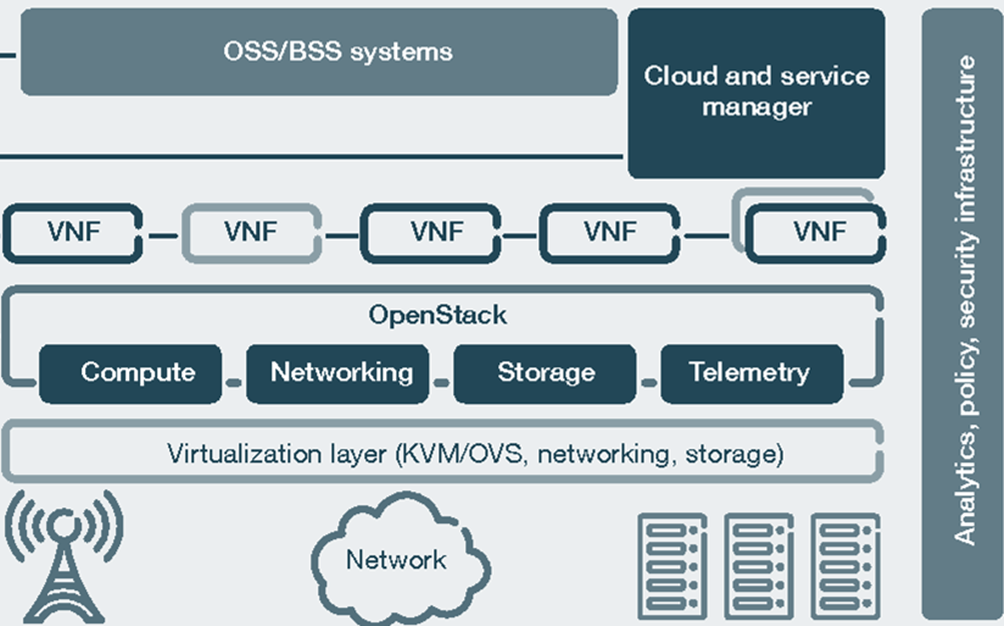
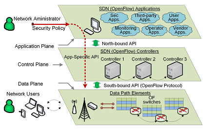
SDN separates the virtualized network infrastructure from its logical architecture. which automates configuration for routing, security etc.
It also helps in the management of infrastructure for scaling and availability.
Software-defined Networking (SDN) and Network Functions Virtualization (NFV) are advancing the deployment of 5G systems. The separation of user and control plane are essentially making the system very modular thereby increasing the application to various traffic types
Network Slicing allows mobile operators to partition a single network into multiple virtual networks. This allow network operator to use one physical network to cater to many kinds of service networks with varrying usecases around bandwidth, network latency, processing, resiliency, business requirnments.
Dynamic Network Slicing allows the network resources like radio networks, wire access, core, transport and edge networks to be divided into multiple logical networks to meet requirnments of diverse use cases. [2]
Horizontal Slicing (Infrastructure Sharing)
Vertical Slicing (QoS Slicing)
The virtual infristructure is shared between different tenants for control and operations ( think IaaS)
Virtualization and slicing allow us to create Service Based Architectures ( SBA). This allows control plane and user plane sepration( CUPS). It also allows sepration between access and core network.
The modular function design allows concurrent access to services as well as decoupling of stateless processors and statefull backend ( database).
[2] J. Zhou, W. Zhao and S. Chen, “Dynamic Network Slice Scaling Assisted by Prediction in 5G Network,” in IEEE Access, vol. 8, pp. 133700-133712, 2020, doi: 10.1109/ACCESS.2020.3010623.
Wi‑Fi is a trademark of the Wi-Fi Alliance. It belongs to the family of radio technologies commonly used for wireless local area networking (WLAN) devices.
Speeds 140 megabits per seconds. Backward compatible with a, b and g.
Transmit up to 4 streams of data, each at a maximum of 150 megabits per second, but most routers only allow for 2 or 3 streams.
Backward compatible with 802.11n and thus others. 450 megabits per second on a single stream. It is also called 5G WiFi because of its frequency band .
Wi-Fi CERTIFIED 6 networks enable lower battery consumption in devices, making it a solid choice for any environment, including smart home and Internet of Things (IoT) uses.
wireless access point (AP) allows wireless devices to connect to the wireless network. takes the bandwidth coming from a router and stretches it so that many devices can go on the network from farther distances away. Gives useful data about the devices on the network, provide proactive security, and serve many other practical purposes.
Wireless routers are hardware devices that Internet service providers use to connect you to their cable or xDSL Internet network. combines the networking functions of a wireless access point and a router.
Mobile hotspot – feature on smartphones with both tethered and untethered connections share your wireless network connection with other devices
Wi-Fi operational range depends on factors such as the frequency band, radio power output, receiver sensitivity, antenna gain and antenna type as well as the modulation techniquea and propagation charestristics of the signal
Transmitter power Compared to cell phones and similar technology, Wi-Fi transmitters are low power devices. In general, the maximum amount of power that a Wi-Fi device can transmit is limited by local regulations, such as FCC Part 15 in the US. Equivalent isotropically radiated power (EIRP) in the European Union is limited to 20 dBm (100 mW).
Antenna An access point compliant with either 802.11b or 802.11g, using the stock omnidirectional antenna might have a range of 100 m.
Key derivation and confirmation: 384-bit Hashed Message Authentication Mode (HMAC) with Secure Hash Algorithm (HMAC-SHA384)
Key establishment and authentication: Elliptic Curve Diffie-Hellman (ECDH) exchange and Elliptic Curve Digital Signature Algorithm (ECDSA) using a 384-bit elliptic curve
striking features of 5G –
entirely IP based
ability to connect 100x more devices ( IOT favourable )
speed upto 10 Gbit/s
high peak bit rate
high data volume per unit area
virtually 0 latency hence high response time
LTE stands for Long Term Evolution and is a registered trademark owned by ETSI (European Telecommunications Standards Institute) for the wireless data communications technology and a development of the GSM/UMTS standards.
Multiplying the capacity of a radio link using multiple transmission and receiving antennas to exploit multipath propagation.Key technology for achieving a vast increase of wireless communication capacity over a finite electromagnetic spectrum. Antenna configuration – implies antenna spatial diversity by useing arrays of multiple antennas on one or both ends of a wireless communication link … Continue reading MIMO ( multiple-input and multiple-output )
LTE stands for Long Term Evolution and is a registered trademark owned by ETSI (European Telecommunications Standards Institute) for the wireless data communications technology and a development of the GSM/UMTS standards.
Both radio and core network evolution
All-IP packet-switched architecture
Standardised by 3GPP
(+) Lower CAPEX ans OPEX involved
LTE evolved from an earlier 3GPP system known as the Universal Mobile Telecommunication System (UMTS), which in turn evolved from the Global System for Mobile Communications (GSM). Also it is aligned with 4G (fourth-generation mobile)
It is backward compatible with GSM/EDGE/UMTS/CDMA/WCDMA systems on existing 2G and 3G spectrum, even hand-over and roaming to existing mobile networks.
Motivation for evolution – Wireless/cellular technology standards are constantly evolving for better efficiency and performance.LTE evolved as a result of rapid increase of mobile data usage. Applications such as voice over IP (VOIP), streaming multimedia, videoconferencing , cellular modemetc.
It provides packet-switched traffic with seamless mobility and higher qos than predecessors. Also high data rate, throughput, low latency and packet optimized radioaccess technology on flexible bandwidth deployments.
Timeline of Evolution
GSM : calls on circuit switching ( CS ) between 2 parties for communication. Dedicated circuits are used for voice and SMS.
GPRS : packet switching (PS) is introduced for data services
UMTS / 3G : network elements begin evolving into PS . No changes to core.
EPC / LTE/VOLTE : No circuit switched domain at all .
Carrier bandwidth : Range from 1.4 MHz up to 20 MHz. Ultimately bandwidth used by carrier depends on frequency band and the amount of spectrum available with a network operator.
Mobility 350 km/h
Coverage 5 – 100km with slight degradation after 30km
LTE architecture supports hard QoS and guaranteed bit rate (GBR) for radio bearers.
Universal Integrated Circuit Card (UICC) : also known as the SIM card for LTE equipments. It runs an application known as the Universal Subscriber Identity Module (USIM).
2. Evolved UMTS Terrestrial Radio Access Network (E-UTRAN)
handles the radio communications between the mobile and the evolved packet core. High level representation for eNodeB or eNB
Role of eNB : sends and receives radio transmissions to all the mobiles using the analogue and digital signal processing functions of the LTE air interface. eNB also controls the low-level operation of all its mobiles, by sending them signalling messages such as handover commands.
3. Evolved Packet Core (EPC)
This sub system resembles IMS environment.
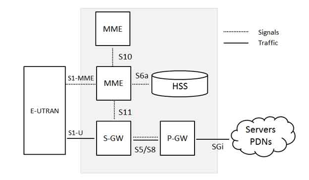
SGW(Serving Gateway) for routing and forwarding of user data packets
Packet Data Network (PDN) Gateway (P-GW) communicates with the outside world simillar to GGSN ( GPRS support node ) and SGSN ( serving GPRS support node ) in UMTS and GSM.
Home Subscriber Server (HSS) is a central database that contains information about all the network operator’s subscribers. Almost simillar to HLR/AAA in 2G /3G architcture.
Mobility management entity (MME) controls the high-level operation.
For a roming user in Visited-PLMN, the user is connected with the E-UTRAN, MME and S-GW of the visited LTE network. However, LTE/SAE allows the P-GW of either the visited or the home network to be used, as shown in below:
For roaming prepaid charging, accounting flows are made to access prepaid customer data, via P-Gateways or CSCF in an IMS environment.
A-SBC (Access Session Border Controller) consists of P-CSCF and ALG/AGW. This connects access network (LTE) to IMS core.
Connect IP networks, including IPv4 and IPv6 interworking, NAT traversal, etc.
Security
DDos prevention
Topology hiding
Encryption
P-CSCF maintains the security associations between itself and the UE
QoS control
trancoding
media service handling using Application layer gateway (ALG) access gateway (AGW)
Core IMS has
I-CSCF (Interrogating Call Session Control Function) which provides Location service to find the correct S-CSCF for each subscriber
for peer networks the I-CSCF is the first point of contact.
S-CSCF (Serving Call Session Control Function) SIP session management and routing
connect to HSS for policies
invokes Application Servers (TAS, IPSMGW)
Telephony Application Server (TAS) is the application layer of the telecommunication system which adds intelligience and business logic to the platform. We can design call flows and usecases such as
Interconnect Session Border Controller (I-SBC) handles the boundary where service providers interconnect and exchange inbound outbound SIP sessions. It consists of
TWAG or ePDG gateway is used to integrate the Wireless LAN access network into the Mobile Network Packet Core – EPC Network.
TWAG (Trusted Wireless Access Gateway) in the Wi-Fi core provides trusted access to the UE( User Equipment). The TWAG is then connected directly to the P-GW (Packet Gateway) in the Evolved Packet Core (EPC).
SISO – Single Input Single Output SIMO – Single Input Multiple output MISO – Multiple Input Single Output MIMO – Multiple Input multiple Output
Multiplying the capacity of a radio link using multiple transmission and receiving antennas to exploit multipath propagation. Key technology for achieving a vast increase of wireless communication capacity over a finite electromagnetic spectrum.
Antenna configuration – implies antenna spatial diversity by useing arrays of multiple antennas on one or both ends of a wireless communication link boost channel capacity. combats multipath fading enhance signal to noise ratio, create multiple communication paths
Applies to wifi IEEE 802.11n (Wi-Fi), IEEE 802.11ac (Wi-Fi) as well as cellular networks HSPA+ (3G) WiMAX (4G) Long Term Evolution (4G LTE) power-line communication for 3-wire installations as part of ITU G.hn standard and HomePlug AV2 specification
Large capacity increases over given bandwidth and S/N resources Greater throughputs on bands below 6 GHz,
multi-user MU-MIMO
simultaneous independent data links to multiple users over a common time-frequency resource
massive MIMO
enable the expansion of the useful spectrum to microwave and millimeter wave bands within the framework of 5G cellular communication.
microdiversity MIMO
MIMO modes (60m)
Diversity – Alamouti algorithm Beam forming – create and aim the antenna pattern electronically Spatial multiplex – use of precoding and shaping to unravel the multipath signals
challenges faced by mobile equipment vendors implementing MIMO in small portable devices.
Functions
3main categories: precoding, spatial multiplexing (SM), and diversity coding.
Precoding
multi-stream beamforming ( signal is emitted from each of the transmit antennas with appropriate phase and gain weighting such that the signal power is maximized at the receiver input ) , increases reception and reduce multipath fading
In line-of-sight propagation, beamforming results in a well-defined directional pattern. However, conventional beams are not a good analogy in cellular networks, which are mainly characterized by multipath propagation. When the receiver has multiple antennas, the transmit beamforming cannot simultaneously maximize the signal level at all of the receive antennas, and precoding with multiple streams is often beneficial. Note that precoding requires knowledge of channel state information (CSI) at the transmitter and the receiver.
Spatial multiplexing
High-rate signal is split into multiple lower-rate streams and each stream is transmitted from a different transmit antenna in the same frequency channel. If these signals arrive at the receiver antenna array with sufficiently different spatial signatures and the receiver has accurate CSI, it can separate these streams into (almost) parallel channels.
increasing channel capacity at higher signal-to-noise ratios (SNR).
Diversity coding
when there is no channel knowledge at the transmitter , a single stream is transmitted. The signal is emitted from each of the transmit antennas with full or near orthogonal coding. Diversity coding exploits the independent fading in the multiple antenna links to enhance signal diversity.
From ARPANET(Advanced Reseracha nd Prjects Agency Network) in 1973 by US dept of defence , invention of HTTP in 19196 and finally evoluation of SIP in 2000 and availiability of broadband ethernet services, the telecom landscape has evolved. As far as infrastructure, services, and contents are concerned, the VoIP industry is witnessing a migration from POTS / PSTN/ Legacy integrations to NGN (Next Generation Network).
NGN was implemented globally as a means to change the cost base, agility and service capabilities of telecoms providers. The evolved architecture for the transition is one that provides flexibility to service providers by enabling them to deploy new services on IP based technologies, while leveraging existing services and infrastructure as long as it makes sense. This post describes the evolution of voice communication in access , transport and session layers respectively.
1G
2G
3G
4G
5G
Year of dev
1970-1984
1980-1999
1990-2002
2002-2010
2010-2015
Launch year
1987 by Telstra Australia
1991 in Finland by Elisa
1998 pre-commercial launched by NTT DoCoMo in Japan , branded as FOMA.
2009 in Stockholm (Ericsson and Nokia Siemens Networks systems)
We see that the speed enhances considerably with every generation- 1G offerd 2.4 kbps, 2G offered 64 Kbps based on GSM, 3G offered 144 kbps – 2 mbps whereas 4G offers 100 Mbps – 1 Gbps with LTE technology.
It is to be noted that one of requirements set by IMT-2000 was that speed should be at least 200Kbps to call it as 3G service and 384kbps ( wth stationary speeds of 2Mbps) for a “true” 3G.
IP transformation in access layer
Note that voice calls in GSM, UMTS and CDMA2000 were circuit switched but with newer technology voice calls became packet switched too and a lot of rereginerring was required.
LTE (Long Term Evolution) is a series of upgrades to existing UMTS technology involving OFDM and MIMO and newer upgrade were called LTE advanced also. Upcoming 5G offers speeds upto 35.46 Gbps.
While 2G introduced services like SMS , MMS , internal roaming , conference calls, call hold and billing based on services e.g. charges based on long distance calls and real time billing which were unheard of in 1G , there were challenges in terms of page load speed for interactive websites .
As 3G came into picture, usecases also enhanced with multimedia features siuch as fast web browsing, maps navigation, email, video downloading, picture sharing and other Smartphone technology
IMS at work from visiting to home locationAccess network agnostic
It is noteworthy that SKYPE provided VoIP services ( since 2003) much before mobile phone had 2G/3G ( 2010). In current times with many fantastic options to choose from( whatapp , FB messenger , insta cht , Viber , Hangouts ..) given the high bandwidth with 4G/5G and mych advanced media / signal processing tech , the glocal voip scene is touching 400 mililion subscribers and looks very attractive with 1.5$ billion market.
The GSM Association (GSMA) of mobile operators and related companies are devoted to supporting the standardising, deployment and promotion of the GSM mobile telephone system. The GSM Association was formed in 1995. It organises GSMA Mobile World Congress, in addition to smaller, targeted events GSMA Mobile Asia Expo and the GSMA NFC & Mobile Money Summit. Spanning more than 220 countries, the GSMA unites nearly 800 of the world’s mobile operators, as well as more than 200 companies in the broader mobile ecosystem, including handset makers, software companies, equipment providers, Internet companies, and media and entertainment organisations.
The 3rd Generation Partnership Project (3GPP) is a collaboration between groups of telecommunications associations, known as the Organizational Partners. The initial scope of 3GPP was to make a globally applicable third-generation (3G) mobile phone system specification based on evolved Global System for Mobile Communications (GSM) specifications within the scope of the International Mobile Telecommunications-2000 project of the International Telecommunication Union (ITU). The scope was later enlarged to
include the development and maintenance of the Global System for Mobile Communications (GSM) including GSM evolved radio access technologies (e.g. General Packet Radio Service (GPRS) and Enhanced Data Rates for GSM Evolution (EDGE))
an evolved third Generation and beyond Mobile System based on the evolved 3GPP core networks, and the radio access technologies supported by the Partners (i.e., UTRA both FDD and TDD modes). an evolved IP Multimedia Subsystem (IMS) developed in an access independent manner
3GPP standardization encompasses Radio, Core Network and Service architecture. The project was established in December 1998 and should not be confused with 3rd Generation Partnership Project 2 (3GPP2), which specifies standards for another 3G technology based on IS-95 (CDMA), commonly known as CDMA2000. The 3GPP support team (also known as the “Mobile Competence Centre”) is located at the European Telecommunications Standards Institute (ETSI) headquarters in Sophia-Antipolis (France).
The Open Mobile Alliance (OMA) is a standards body which develops open standards for the mobile phone industry. Network-agnostic : The OMA only standardizes applicative protocols; meant to work with any cellular network technologies being used to provide networking and data transport. These networking technology are specified by outside parties. In particular, OMA specifications for a given function are the same with either GSM, UMTS or CDMA2000 networks. Legal status :The OMA is a British limited company.
Standard specifications The OMA maintains a number of specifications, including
Browsing specifications, now called “Browser and Content”, previously called WAP browsing. In their current version, these specifications rely essentially on XHTML Mobile Profile.
MMS specifications for multimedia messaging
OMA DRM specifications for Digital Rights Management
OMA Instant Messaging and Presence Service (OMA IMPS) specification, which is a system for instant messaging on mobile phones (formerly known as Wireless Village).
OMA SIMPLE IM Instant messaging based on SIP-SIMPLE
OMA CAB Converged Address Book, a social address book service standard.
OMA CPM Converged IP Messaging
OMA Client Provisioning (OMA CP) specification for Client Provisioning.
OMA Data Synchronization (OMA DS) specification for Data Synchronization using SyncML.
OMA Device Management (OMA DM) specification for Device Management using SyncML.
OMA BCAST specification for Mobile Broadcast Services.
OME RME specification for Rich Media Environment.
OMA PoC specification for Push to talk Over Cellular (called “PoC”).
OMA Presence SIMPLE specification for Presence based on SIP-SIMPLE.
OMA Service Environment
FUMO Firmware update
SUPL, an IP-based service for assisted GPS on handsets
MLP, an IP-based protocol for obtaining the position/location of mobile handset
WAP1, Wireless Application Protocol 1, 5-layer stack of protocols
The IP Multimedia Subsystem (IMS) Profile for Voice and SMS, documented in this Permanent Reference Document (PRD), defines a profile that identifies a minimum mandatory set of features which are defined in 3GPP specifications that a wireless device (the User Equipment (UE)) and network are required to implement in order to guarantee an interoperable, high quality IMS-based telephony service over Long Term Evolution (LTE) radio access. The scope includes the following aspects:
· IMS basic capabilities and supplementary services for telephony. · Real-time media negotiation, transport, and codecs. · LTE radio and evolved packet core capabilities. · Functionality that is relevant across the protocol stack and subsystems.
This document defines a voice over IMS profile by listing a number of Evolved Universal Terrestrial Radio Access Network (E-UTRAN), Evolved Packet Core, IMS core, and UE features which are considered essential to launch interoperable IMS based voice. The defined profile is compliant with 3GPP specifications.
On premise private branch exchanges ( PBX ) were the first kind of business telephone systems to which the analog PSTN systems of the company were conneced. These analog circuits were then replaced by digital PBX which provided enhanced features liek screening , voicemails , shared lines.
In the current landscape , the digital PBX of the company is connected to the external telco privider via a SBC or SIP trunking service .
An ompremise LAN based voIP system can be accessed from outside via a VPN on SSL/ IPsec. Although it incures greater CAPEX but ensufe maximum control and ownership of the data . Many time the local laws mandate the server to be hosted with a partuclat geographical area too where an on premise setup and data centre is used.
Enterprise communication shifts from on-premise to SaaS (cloud)
As for remote worksforce and employees working from home (such as during lockdown , pandemics ) it is even more crticial for enterprises to maange inter communication between teams and keep the communication private ie not using piblic messaging platforms , hence the role of cloud based PBX integrated with secure and end to end encrypted telco providers is of prime importance .
To read how a SME can setup their own flexible and scable enterprise comunication system read –
With the advent of other disruptive technologies such as free and opensource codecs in browser with WebRTC and well defined framework and standards , voIP definetly looks detsined to expand by leaps and bounds.
Second generation or 2G of telecom emerged a decade after (1990) its predecessor 1G (1980). Although the history of telecom evolution truely beings with internet and further engineered with PSTN, analog voice and switches we shall omit them discussing here as they are truly legacy now. You can read more about Legacy telecom here-
I use the term legacy telecom system many a times , but have not really described what a legacy system actually is . In my conferences too I am asked to just exactly define a … Continue reading Legacy Telecom Networks
We have seen the evolution of teelcom access networks through generations happening pretty quickly recently. While earlier it was a decade that led to the jump between generations, the recent jumps from 3G to 4G to 5G happening fairly quickly. In this article let us dive into what enhancements went into 2G and its successor 3G, since
Where 2G is referred to as the GSM era , 2.5 G as the GPRS with GSM era. The following two diagram denote the service operators architecture nodes in both these times .
2G / GSM era
As compared to its predecessor 1G which used FDMA ( Frequency Division Multiplexing ) for channelization , 2G used used TDMA and CDMA for dividing the channels .
Note that in pure 2G there was only circuit switched communication services .
2.5G or GPRS era
The advent of 2.5 G, in later part of 1990s, bought packet switching for data access along with existing circuit switching for voice network. While 1G and pure2G relied solely on circuit switching, now 2.5 G used both circuit switched and packet switching. The speed provided by General Packet Radio Service ( GPRS ) was ~= 50 Kbps.
Digital voice was introduced with multiple access technologies like CDMS ( Core Division Multiple access )
2.75G ( EDGE)
EDGE( Enhanced Data Rates for GSM evolution) was deploying on GSM technologies and was also standardised by 3GPP technologies . EDGE delivers higher bit-rates per radio channel, resulting in a threefold increase in capacity and performance compared with an ordinary GSM/GPRS connection with speed upto 1 Mbps.
In terms of transmission techniques, EDGE and its varients used Gaussian minimum-shift keying (GMSK), EDGE uses higher-order PSK/8 phase shift keying (8PSK) for the upper five of its nine modulation and coding schemes.
Note that the processes such as billing etc had begun merging for both the circuit switched and packet switched networks .
3G
Even though 2G evolution was enough to sustain voice abd video calls, the mobile industry became “smarter” and data hungry for faster services ( mobile gaming , video conferencing ,video streaming, social media interactions are some of the usecases ). It became necessary to bring in faster speed while evolving towards and hence was born 3G in early 20000. Some of the tecehnolgies which were branded 3G are
UMTS (Universal Mobile Telecommunications System)
Core technology for 3G ,
CDMA2000
3.5G ( HSPA)
Now 3G was further succeeded by 3.5G ( HSPA – High Speed Downlink Packet Access ) with max theoritical 21.6 Mbps.
Eventually 4G ( LTE Long Term Evolution ) overtook the indutry with newer technologies but the impressive array of technologies in transaition between 2G to 3G to 4G was awe inspirinig indeed .
LTE stands for Long Term Evolution and is a registered trademark owned by ETSI (European Telecommunications Standards Institute) for the wireless data communications technology and a development of the GSM/UMTS standards.
striking features of 5G –
entirely IP based
ability to connect 100x more devices ( IOT favourable )
speed upto 10 Gbit/s
high peak bit rate
high data volume per unit area
virtually 0 latency hence high response time
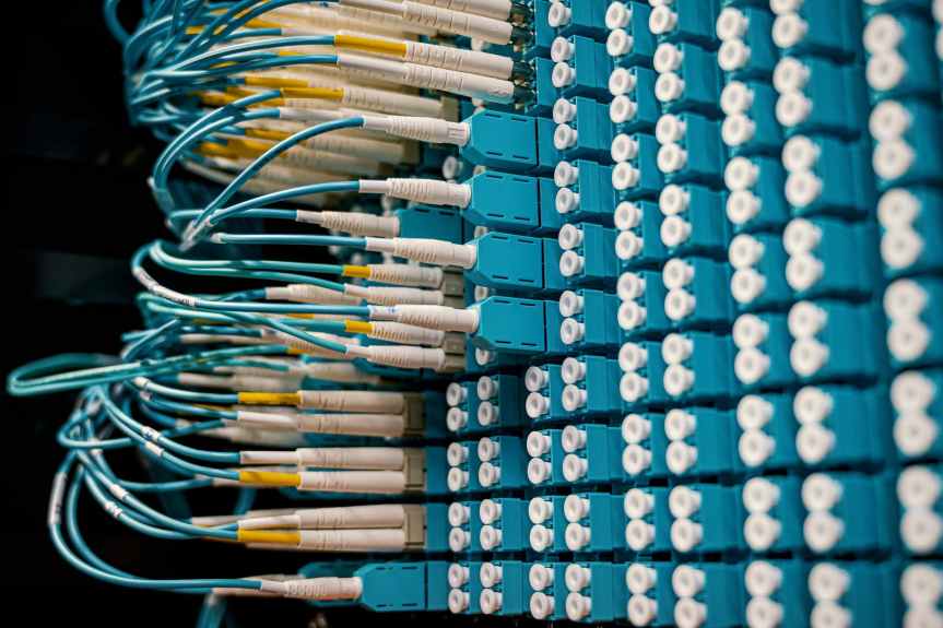
Layer 1 Equipment : Physical mediums copper ethernet cables, fiber optic, ethernet hubs or even wireless mediums such as WiFi Bluettoth , Microwave , IR( Infra Red )Remote or other over the air technologies.
Factors affecting physical layer protocols could be Wiring standards such as T568A and B for Ethernet Radio frequencies such as Wi-Fi, BLE, Zigbee , LORA
Layer 2 links or transmistts data between nodes in a network, it involves protocol like FrameRelay.
The sublayers of this layer are
2A. MAC ( Medium Access control) : prevent collision in half duplex network. Although half duplex is non existant now, duplex negotations have simmilar collision avoidance.
2B. LLC ( Logical Link Control) : mechanisms for multiplexing Layer 3 Protocol such as it can acts as interface between the media access control sublayer and the network layer.
Layer 2 Data : The data packets are usally referred to as Frames and are structured to have a header containing source and destination adress as well as payload. VLAN(Virtual LAN) implemeted atop this layer protcols helps to split up broadcast domains by allowing to sedment devices to their own dedicated LAN.
Layer 2 Equipment : More intelligent than Layer 1 – Switches , Bridges , Network Card. While a hub ( Layer 1 ) would simply broadcast traffic to all ports, a Switch could read the destnation MAC address and only forward to the specific port that MAC address is linked to.
This layer defines a logical address of an endpoint. Unlike MAc address ( from Layer 2 ) which is fixed for a device and assigned onetime by the vendor during the manufacturing process, Layer 3 endpoints are not fixed and could be a static IP configuration or a DHCP automated configuration
Layer 3 Data : Organization of Data at this layer is referred to as a packet, which is a stateless grouping of data
Layer 3 Equipment : Firewalls can operate on this layer( can operate on upper layers too) using stateless static filtering.
While some protocol are layer specifc other can operate in multiple layers such as MultiLayer Switch which make decision based on following : – MAC address and Protocol field in L2 data link frame – IP address and Protocol field in L3 network layer header – Port numbers in L4 transport layer header
Hardware-based switches, which use the MAC address of the host’s network interface cards (NICs) to decide where to forward frames. Mostly carried out without frame modification unless the frame needs to be encapsulated for a different medium such as wired to wireless.
(+) Efficient since they have least modificatons to frame
(-) acting as multipot brdges causes performance issues. Increasing size of network and slow convergence of spanning tree is probelmatic for such using broadcast/multicast.
Determine paths based on logical addressing. These also check and recompute layer-3 header checksums and examine and update the time to live (TTL) field for validity. Network switches can perform almost all of the functions of a router however they are designed for the specific physical medium.
(+) lower network latency as a packet can be routed without making extra network hops to a router.
Recognize application level transactions and may use URL to distribute load, also using a cache such as CDN ( Content Delivery Network).
Switches operating on higher layers, also referred to by some vendors as AppSwitches, can route packets based on application information can provide superior quality of service (QoS) for IP voice and media streams. It can help with domain-specific load-balancing capabilities for voice-over-IP gateway and IP PBX ( eg packet-tagging techniques, SIP handlers to prioritize, Differentiated Services ).