“ The Internet of Things (IoT) is the network of physical objects or “things” embedded with electronics, software, sensors and connectivity to enable it to achieve greater value and service by exchanging data with the manufacturer, operator and/or other connected devices. “ – wikipedia
Smart TV , mobiles , CCTV cams and other few things are already connected to the Internet.So whether we’ve known it or not, the “Internet of Things” is already here. But , number of these interconnections is on the rise and need to controlled , monitored and optimized .
IOT areas where media streaming capabilities of
- Home automation
- Targeted marketing
- Wildlife and environment
- Manufacturing
- Smart Grid / real-time energy optimization.
- Connected logistics
- Augmented reality
- Ubiquitous computing (ubicomp) / BYOD
- Healthcare
- Transportation / connected car
This post describes the process of creating a Arduino based IOT control setup over Internet. The features of this application are
- Cheap and more customized solution to specific use cases
- Recycled components
- No patented or proprietary protocols
- Easy person-to-machine and machine-to-machine comm.
- Can be integrated with other modules like Recording , Multiplexing , transcoding .
Requirements :
Hardware requirements
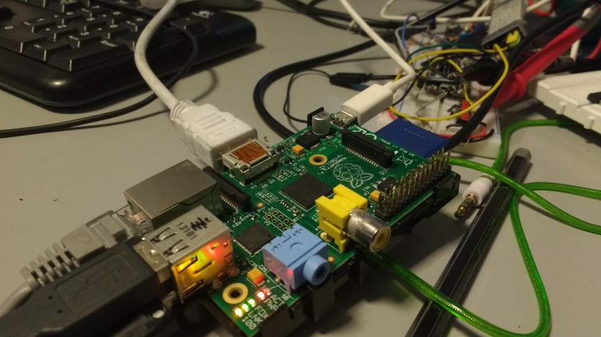
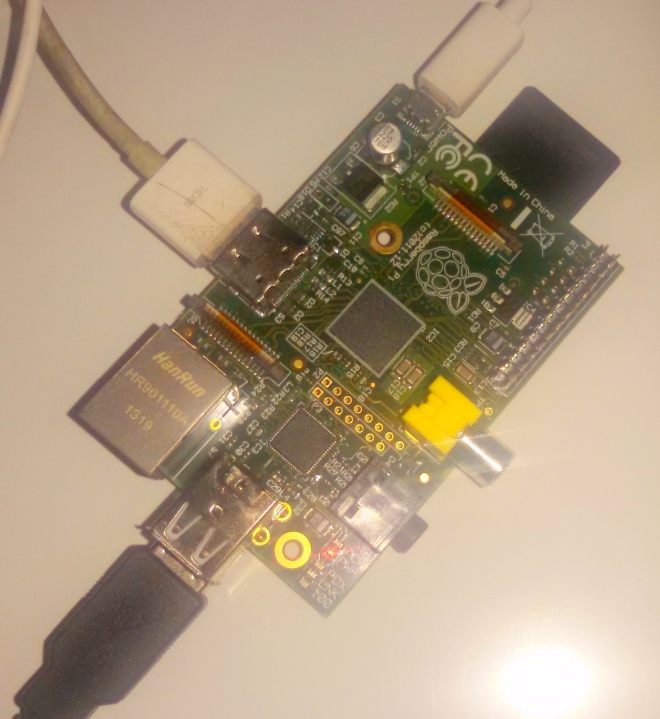
- Rpi as communication hub to internet
- ultrasonic sensors to detect obstruction in field of view
- camera module of Rpi or standrad webcam
- Motion Sensors
- Buzzer
- mic
- flash lights connected via relay drivers to rpi
Software requirements
- open CV ( image processing)
- Simple CV ( face recognition )
- motion
- webrtc for media live streaming in case of remote monitoring
WebRTC communication and media streaming setup
Raspberry Pi Communication Modules
Ethernet
Ethernet wires can connect rpi to a another machine such as laptop from which it can be connected via terminal or using remote desktop accessing software’s such as tightvnc .

Undoubtedly Ethernet offers the fastest speed, lowest latency and no data loss due to wireless interference problems however it is as the price of being immobile , as its is a wired connection and shifting disrupts the connection .
Cat-5e cable and Cat-6e cable can offer upto 1 Gb/s and 10 Gb/s respecctively .
Wifi or IEEE 802.11 
Wi-Fi was launched in the year 1997. Victor Hayes is known as father of Wi-Fi.
There are various standards and adoptions for IEEE802.11 like 802.11ac, 802.11n, 802.11g, and 802.11b which can offer maximum speeds of 866.7 Mbit/s , 150 Mbit/s , 54 Mbit/s and 11 Mbit/s respectively , however consumes more power than Bluetoooth .
Image Wifi hotspot

Image Wifi USB

Image Wifi module Rpi
Wifi -direct can even reach upto 250mbps of data transferring rate at 2.4, 3.6 and 5 GHz frequency . Range is around 100m .
BLE / Bluetooth 
Bleutooth was launched in 1994 as a wireless communication alternative to RS232 by Ericsson . Now it is handled by Special Interest group for Bluetooth.
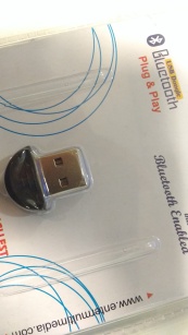
Bluetooth 4.0 can do data transfer rates to be upto 25mbps at 2.4GHz frequency while maximum range being 30 m .
GSM / GPRS
This section refers to the data provider by the network of a telecom carrier company such as Airtel , Tata Docomo etc in India . 2G capabilities

Majorly the technology behind the differnt generation of telecom is as follows
2G – GSM 900, GSM 1800 – 14.4 kbps
3G – UMTS 2100 – 3.1 Mbps
4G – LTE 850 (5), LTE 1800 (3), LTE 2300 (40) – 100 Mbps
The carries frquency varries from 200 KH , 5 MHz , 15 MHz recpectively
NFC
Short for Near Field Communication . NFC uses electromagnetic induction between two loop antennae in smart devices to exchange information.
It uses unlicensed radio frequency ISM band of 13.56 MHz with data trabsfer rate of about 106 to 424 kbit/s.Unlike bluetooth it is a point to point communication .
Audio / Video Streaming
First enable the rpi camera support from the boot screen

One can choose between the following ways to be able to stream data from a Rpi
-
Motion
To start motion detection edit motion.cong file
$ vi /etc/motion/motion.conf
Although the it starts detecting motion automatically we can modify few properties like
# Threshold for number of changed pixels in an image that
# triggers motion detection (default: 1500)
threshold 1500
# Detect motion in predefined areas (1 – 9). Areas are numbered like that: 1 2 3
# A script (on_area_detected) is started immediately when motion is 4 5 6
# detected in one of the given areas, but only once during an event. 7 8 9
# One or more areas can be specified with this option. Take care: This option
# does NOT restrict detection to these areas! (Default: not defined)
; area_detect value
# Picture frames must contain motion at least the specified number of frames
# in a row before they are detected as true motion. At the default of 1, all
# motion is detected. Valid range: 1 to thousands, recommended 1-5
minimum_motion_frames 1
# Specifies the number of pre-captured (buffered) pictures from before motion
# was detected that will be output at motion detection.
# Recommended range: 0 to 5 (default: 0)
# Do not use large values! Large values will cause Motion to skip video frames and
# cause unsmooth movies. To smooth movies use larger values of post_capture instead.
pre_capture 10
# Number of frames to capture after motion is no longer detected (default: 0)
post_capture 10
# Event Gap is the seconds of no motion detection that triggers the end of an event.
# An event is defined as a series of motion images taken within a short timeframe.
# Recommended value is 60 seconds (Default). The value -1 is allowed and disables
# events causing all Motion to be written to one single movie file and no pre_capture.
# If set to 0, motion is running in gapless mode. Movies don’t have gaps anymore. An
# event ends right after no more motion is detected and post_capture is over.
event_gap 60
# Maximum length in seconds of a movie
# When value is exceeded a new movie file is created. (Default: 0 = infinite)
#max_movie_time 0
max_mpeg_time 240
# Always save images even if there was no motion (default: off)
emulate_motion off
To beep when motion is detected
Note: Motion never beeps when running in daemon mode.
quiet off
To draw a identifiable area where motion is deceted
# Set the look and style of the locate box if enabled.
# Valid values: box, redbox, cross, redcross (default: box)
# Set to ‘box’ will draw the traditional box.
# Set to ‘redbox’ will draw a red box.
# Set to ‘cross’ will draw a little cross to mark center.
locate_motion_style box
2.WebRTC ( rpi model 2 onwards)
In terminal:
$ curl http://www.linux-projects.org/listing/uv4l_repo/lrkey.asc | sudo apt-key add -
add this to /etc/apt/sources.list :
deb http://www.linux-projects.org/listing/uv4l_repo/raspbian/ wheezy main
or simply run
wget http://www.linux-projects.org/listing/uv4l_repo/lrkey.asc && sudo apt-key add ./lrkey.asc

Update the repos
$ sudo apt-get update
Now install uv4l and supported software
$ sudo apt-get install uv4l uv4l-raspicam
If you want the driver to be loaded at boot, also install this optional package:
$ sudo apt-get install uv4l-raspicam-extras
Most importantly install the uv4l server and the WebRTC extension for the Streaming Server
$ sudo apt-get install uv4l-webrtc

Type uv4l –help for getting list of options for core , streaming , fine tuning , logging etc
start the service using following command
sudo service uv4l_raspicam start

Open web
http://<rpi ip address>:8080/conference

Once the media capture and stream is established it is important to decide the stream methodology such as relay through a centralized media server or mesh streaming network as in webrtc p2p.
Click on any of the given options to see a incoming media stream from rpi
For example
Webrtc :
http://<rpi_ip>:8080/stream/webrtc gives incoming Webrtc media stream.
MJpeg
http://<rpi_ip>:8080/stream/video.mjpeg gives mjpeg
The default server config is
- basic HTTP/HTTPS authentication: disabled
- underlying video device node: /dev/video0
- current connections: 1, queued: 0, total handled: 11
- max. simultaneous streams allowed: 3, max. threads: 5
- raw HTTP/HTTPS video streams in MJPEG, JPEG (continuous stills) and H264 formats – if supported – are available under the /stream/video.mjpeg, /stream/video.jpeg, and /stream/video.h264URL paths respectively
Note : https is required if you want to have a outgoing video from your computer to rpi as browser mandates secure origin but https is not required for an incoming video stream so you can easily view the rpi genrated webrtc video without being on https .

