Surajdroid ( Ramudroid v7 Solar Powered )

Ramudroid is an ingeniously build robot to clean outdoors and alleys inspired by Bharat Swachhata Abhiyaan . Read more

Prototype in Development

Stages include, assembly of frame and wheels , attaching bin and equalising weight distribution , adding circuits for drivers , relays , micro processors and controllers . Finally attaching power sources – solar panel and a standby battery for the micro controller so that it can communicate remotely without any solar power too.

Frame and wheel
Side view of Robot
solar panel mounted

Algorithm Enhancements

Exprimentation with Obstruction Detection .

  • Ultrasonic senors – primitive
  • LiDar – depth sending
  • Steroscopic vision – dual camras
  • train model to idnetify walls, poles , tree , tyres

Experimentation to find if tray is full and Stop Operation , retreat to dumping point

  • Tray Weight reaching threshold
  • Marker point detction

Pause operation and take Shelter in Rain

  • Rain sensors

Equipment Cost

Power And Charge Devices

  1. Solar Panel MicroSun MS 12v 60 WP – 2500 INR
  2. Solar charger Controller – 600 INR
  3. Battery 11.1 V 2200 mAh – 500 INR

Frame and Motion Assembly

  1. Wheels 10 cm diameter – 50 INR x 4 ie 200 INR
  2. Tray – 400 INR
  3. Frame Assembly – 1000 INR
  4. Arduino to control Motors Drivers – 500 INR
  5. Motor Driver – 300 INR
  6. LCD display – 200 INR

Electronics , Communicating modules and Sensors

  1. Raspberry Pi Moddel B+/ 4 -2700 INR
  2. GPS module – 700 INR
  3. GSM module – 1400 INR
  4. Camera 5 MP Board Module – 450 INR

Total Cost to Develop – 12000 INR

Working Principle

The robot is divided into 2 parts – Cleaning Unit and driving unit

Driving Unit

Consists of 4 wheel to drive the setup . Wheels must be tightly fixed into position to prevent them from tilting, spreading outwards and imbalancing the load. 2 rear controller by 12 V 1 amp DC motors with 300 RPM and 2 front free wheels. Motors are conneted to Arduino for receving command for start , stop , left or right navigation.

There are three input pins for each motor, including Input1 (IN1), Input2 (IN2), and Enable1 (EN1) for Motor1 and Input3, Input4, and Enable2 for Motor2.

IN 1IN2Motor
00Brake
10Forward
01Backward
11Move

Cleaning Unit

Uses 3 tough bristled brushes controlled by 3 5V DC gear motors with 60 RPM. The arrangement of the brushes is such that the bottom 2 brushes use clockwise and anticlockwise motion outwards to pull in the litter and push up with the flow of the air and bristles of the brush. The third brush combs the collected into the collector tray. The tray is attached to weight control system to stop operations when critical weight is reached to prevent overloading the robot

Solar specification

  • Maximum Power (Pmax) – 60 Wp
  • Voltage at Maximum Power (Vmpp) – 18.1 V
  • Current at Maximum Power (Impp) – 3.32 A
  • Open Circuit Voltage (Voc) – 22.32 V
  • Short Circuit Current (Isc) – 3.63 A
  • Standard Test Conditions (STC): air mass AM 1.5, irradiance 1000W/m2, cell Temperature 25°C
  • Maximum System Voltage 1000 V

Electrical Data at NOCT

  • Temperature – 47±2 °C
  • Nominal Operating Cell Temperature (NOCT): 800W/m2, AM 1.5, windspeed 1m/s,ambient temperature 20°C

Thermal Ratings

  • Operating Temperature Range -20~90 °C
  • Temperature Coefficient of Pmax -0.43 %/°C
  • Temperature Coefficient of Voc -0.36 %/°C
  • Temperature Coefficient of Isc 0.66 %/°C

Material Data

  • Panel Dimension (H/W/D) 705x655x35 mm
  • Weight 6 kg
  • Cell Type Polycrystalline
  • Cell Size 156×156 mm
  • Cell Number 36
  • Encapsulant Type – EVA ( Ethylene vinyl acetate)
  • Frame Type Anodized Aluminium Alloy

Physical

  • Dimentions – 70mm x 655mm x 35mm
  • cells per module – 36
  • cell type – poly crystalline sIlicon
  • fuel cell dimention – 156mm x 156mm
  • Encapsulation – EVA
  • back cover – PV sheet

Ref : https://www.enfsolar.com/pv/panel-datasheet/crystalline/20863

Load

  • Solar panel weight – 5kg with annodixed alumium frame , 3 kg without the frame with just the toughened texture glass on panel
  • Frame and wheels – 2kg
  • Accessories – 1 kg
  • Garbage holding capacity – 2 kg
  • Total Weight of the Robot : maximum upto 10Kg

Scenarios

Good Sunlight scenario : This 12 Volt solar panel provide about 2.5 Amps of current on average during daytime. In such a situtaion it is directly used to drive the machine’s motors for wheels and brushes and electrical components such as PI and arduino. In no motion of rest conditions the genrated power is used to charge the attached backup battery.

Shady / evening / morning scenario : When the panel is not receiving direct or strong sunlight, the power generated is less hence not sufficient to take the load of driving the wheels for movement. Hence is the power falls below a certain prespecified threhold, the current is drawn from battery backup.

Night / No sunlight Scenario : battery is used to power the setup. panel can be dismounted to lower the load.

Contributing to Ramudroid Project or Reuse

It is deigned and developed as an MIT licensed Opensourced product by a bunch of developers and engineers in Bangalore for greater good.

https://github.com/altanai/Ramudroid

RamuDroid

Bot to clean roads and outdoors for a better and cleaner India. It lifts up small objects like plastic cups,wrappers,leaves etc.

ramudroid image.png

The droid also provides real-time camera stream and detects obstruction to re-route itself. It can communicates over GSM ,wifi and BLE . It can also be remote navigated via browsers or android.

Working :

stages of ramudroid

  1. Litter comes between rotating brushes
  2. Litter is picked by brushes and pushed upwards  
  3. Brushes push it towards the tray

Is is inspired by Swach Bharat Abhiyaan in India , its an effort to contribute to society and welfare and well-being through technology . Following are some diagrams for the current and the previous versions , along with major delta points .


RamuDroid v1.0

Remote Streaming and movement via motors switched manually. Communication over Ethernet.

Ramudroidv1.0.jpg

Dashboard /console Screen

RamuDroid v1  console


v3.0

Cleaning garbage on public roads and outdoors through robot . Remote navigation and control of control through web page and camera live streaming .

Ramudroid compoenet diagram v5

v3 web console

Screenshot from 2015-12-03 08:55:27.png


v6

Clean roads , pick up litter ( wrappers, leaves , cups , plastics bits etc ) . communicated over BLE ,Wifi and 3G n/w . Auto buzzer when meet with an obstruction in way . Flash Lights . Enhanced Design .

Ramudroid 6.5 componet diagram


Web Dashboard:

Screenshot from 2016-03-19 04-28-53.png

Pin Diagram associated with activities

Pin Pin 0 Pin 1 Pin 2 Pin 3 Pin 4 Pin 5 Pin 6 Pin 7
Front 0 1 0 1 1 1 1 1
Back 1 0 1 0 1 1 1 1
Left 1 0 1 0 1 1 1 1
Right 1 0 1 0 1 1 1 1
Brushes ON 1 0 1 0 1 1 1 1
Brushes OFF 1 0 1 0 1 1 1 1
Lift ON 1 0 1 0 1 1 1 1
Life OFF 1 0 1 0 1 1 1 1


Github : https://github.com/altanai/m2mcommunication

Slideshare :

Twitter :https://twitter.com/search?q=%23ramudroid


IOT Survillance with Arduino + Rpi + WebRTC

“ The Internet of Things (IoT) is the network of physical objects or “things” embedded with electronics, software, sensors and connectivity to enable it to achieve greater value and service by exchanging data with the manufacturer, operator and/or other connected devices. “ – wikipedia

Smart TV , mobiles , CCTV cams and other few things are already connected to the Internet.So whether we’ve known it or not, the “Internet of Things” is already here. But , number of these interconnections is on the rise and need to controlled , monitored and optimized .

IOT areas where media streaming capabilities of

  • Home automation
  • Targeted marketing
  • Wildlife and environment
  • Manufacturing
  • Smart Grid /  real-time energy optimization.
  • Connected logistics
  • Augmented reality
  • Ubiquitous computing (ubicomp) / BYOD
  • Healthcare
  • Transportation / connected car

This post describes the process of creating a Arduino based IOT control setup over Internet. The features of this application are

  1. Cheap and more customized solution to specific use cases
  2. Recycled components
  3. No patented or proprietary protocols
  4. Easy person-to-machine and machine-to-machine comm.
  5. Can be integrated with other modules like Recording , Multiplexing , transcoding .

Requirements :

Hardware requirements

  1. Rpi as communication hub to internet
  2. ultrasonic sensors to detect obstruction in field of view
  3. camera module of Rpi or standrad webcam
  4. Motion Sensors
  5. Buzzer
  6. mic
  7. flash lights connected via relay drivers to rpi

Software requirements

  1. open CV ( image processing)
  2. Simple CV ( face recognition )
  3. motion
  4. webrtc for media live streaming in case of remote monitoring


Screenshot from 2015-11-10 22:02:25

Screenshot from 2015-11-11 11:22:09

WebRTC communication and media streaming setup

Screenshot from 2015-11-11 11:31:30

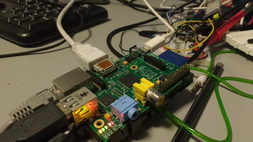
Raspberry Pi Communication Modules


Ethernet

Ethernet wires can connect rpi to a another machine such as  laptop  from which it can be connected via terminal or using remote desktop accessing software’s such as tightvnc .

ethernet

Undoubtedly Ethernet offers the fastest speed, lowest latency and no  data loss due to wireless interference problems however it is as the price of being immobile , as its is a wired connection and shifting disrupts the connection .

Cat-5e cable and  Cat-6e cable can offer upto  1 Gb/s and  10 Gb/s respecctively .

Wifi or IEEE 802.11  wifi

Wi-Fi was launched in the year 1997. Victor Hayes is known as father of Wi-Fi.

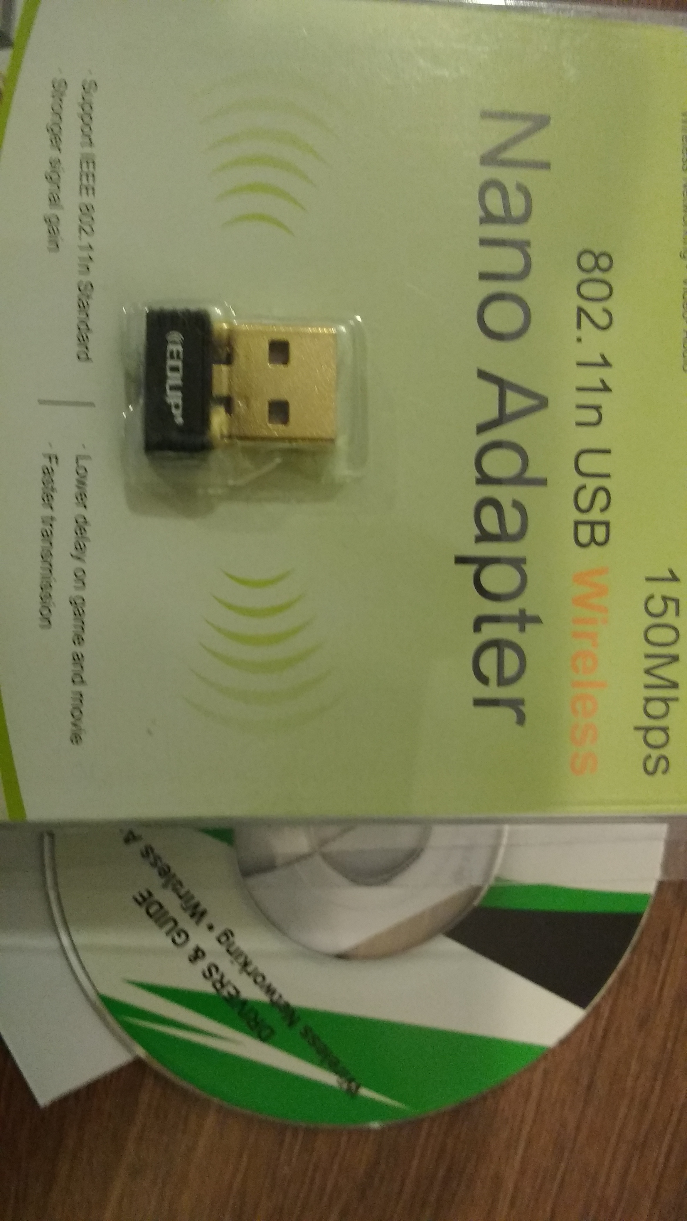
There are various standards and adoptions for IEEE802.11 like 802.11ac, 802.11n, 802.11g, and 802.11b which can offer maximum speeds of 866.7 Mbit/s , 150 Mbit/s  ,  54 Mbit/s and 11 Mbit/s respectively , however consumes more power than Bluetoooth .

Image Wifi hotspot

wifi

Image Wifi USB

wifi2

Image Wifi module Rpi

Wifi -direct can even reach upto 250mbps of data transferring rate at  2.4, 3.6 and 5 GHz frequency . Range is around 100m .

BLE / Bluetooth ble

Bleutooth was launched in 1994 as a wireless communication alternative to RS232 by  Ericsson . Now it is handled by Special Interest group  for Bluetooth.

ble

Bluetooth 4.0 can do data transfer rates to be upto 25mbps  at 2.4GHz frequency  while maximum range being 30 m .

GSM / GPRS

This section refers to the data provider by the network of a telecom carrier company such as Airtel , Tata Docomo etc in India . 2G capabilities

gsm

Majorly the technology behind the differnt generation of telecom is as follows
2G – GSM 900, GSM 1800 – 14.4 kbps
3G – UMTS 2100 – 3.1 Mbps
4G – LTE 850 (5), LTE 1800 (3), LTE 2300 (40) – 100 Mbps

The carries frquency varries from 200 KH , 5 MHz , 15 MHz recpectively

NFC

Short for Near Field Communication . NFC uses electromagnetic induction between two loop antennae in smart devices to exchange information.
It uses unlicensed radio frequency ISM band of 13.56 MHz with data trabsfer rate of about 106 to 424 kbit/s.Unlike bluetooth it is a point to point communication .

Audio / Video Streaming

First enable the rpi camera support from the boot screen

rpi_camera._support

One can choose between the following ways to be able to stream data from a Rpi

  1. Motion

To start motion detection edit motion.cong file

$ vi /etc/motion/motion.conf

Although the it starts detecting motion automatically we can modify few properties like

# Threshold for number of changed pixels in an image that
# triggers motion detection (default: 1500)
threshold 1500
# Detect motion in predefined areas (1 – 9). Areas are numbered like that: 1 2 3
# A script (on_area_detected) is started immediately when motion is 4 5 6
# detected in one of the given areas, but only once during an event. 7 8 9
# One or more areas can be specified with this option. Take care: This option
# does NOT restrict detection to these areas! (Default: not defined)
; area_detect value

# Picture frames must contain motion at least the specified number of frames
# in a row before they are detected as true motion. At the default of 1, all
# motion is detected. Valid range: 1 to thousands, recommended 1-5
minimum_motion_frames 1

# Specifies the number of pre-captured (buffered) pictures from before motion
# was detected that will be output at motion detection.
# Recommended range: 0 to 5 (default: 0)
# Do not use large values! Large values will cause Motion to skip video frames and
# cause unsmooth movies. To smooth movies use larger values of post_capture instead.
pre_capture 10

# Number of frames to capture after motion is no longer detected (default: 0)
post_capture 10

# Event Gap is the seconds of no motion detection that triggers the end of an event.
# An event is defined as a series of motion images taken within a short timeframe.
# Recommended value is 60 seconds (Default). The value -1 is allowed and disables
# events causing all Motion to be written to one single movie file and no pre_capture.
# If set to 0, motion is running in gapless mode. Movies don’t have gaps anymore. An
# event ends right after no more motion is detected and post_capture is over.
event_gap 60

# Maximum length in seconds of a movie
# When value is exceeded a new movie file is created. (Default: 0 = infinite)
#max_movie_time 0
max_mpeg_time 240

# Always save images even if there was no motion (default: off)
emulate_motion off
To beep when motion is detected
Note: Motion never beeps when running in daemon mode.
quiet off

To draw a identifiable area where motion is deceted
# Set the look and style of the locate box if enabled.
# Valid values: box, redbox, cross, redcross (default: box)
# Set to ‘box’ will draw the traditional box.
# Set to ‘redbox’ will draw a red box.
# Set to ‘cross’ will draw a little cross to mark center.

locate_motion_style box


2.WebRTC ( rpi model 2 onwards)

In terminal:

$ curl http://www.linux-projects.org/listing/uv4l_repo/lrkey.asc | sudo apt-key add -
add this to /etc/apt/sources.list : 
deb http://www.linux-projects.org/listing/uv4l_repo/raspbian/ wheezy main 

or simply run

wget http://www.linux-projects.org/listing/uv4l_repo/lrkey.asc && sudo apt-key add ./lrkey.asc

linuxProject

Update the repos

 $ sudo apt-get update

Now install uv4l and supported software

 $ sudo apt-get install uv4l uv4l-raspicam

If you want the driver to be loaded at boot, also install this optional package:

 $ sudo apt-get install uv4l-raspicam-extras


Most importantly install the uv4l server and the WebRTC extension for the Streaming Server

 $ sudo apt-get install uv4l-webrtc

Screenshot from 2016-06-19 15-24-00

Type uv4l –help for getting  list of options for core , streaming , fine tuning , logging etc

start the service using following command


sudo service uv4l_raspicam start

Screenshot from 2016-06-19 15-41-10

Open web
http://<rpi ip address>:8080/conference

Screenshot from 2016-06-19 15-41-34

Once the media capture and stream is established it is important to decide the stream methodology such as relay through a centralized media server or mesh streaming network as in webrtc p2p.

Click on any of the given options to see a incoming media stream from rpi

For example

Webrtc :

http://<rpi_ip&gt;:8080/stream/webrtc  gives incoming Webrtc media stream.

MJpeg

http://<rpi_ip&gt;:8080/stream/video.mjpeg gives mjpeg


The default server config is

  • basic HTTP/HTTPS authentication: disabled
  • underlying video device node: /dev/video0
  • current connections: 1, queued: 0, total handled: 11
  • max. simultaneous streams allowed: 3, max. threads: 5
  • raw HTTP/HTTPS video streams in MJPEG, JPEG (continuous stills) and H264 formats – if supported – are available under the /stream/video.mjpeg, /stream/video.jpeg, and /stream/video.h264URL paths respectively

Note : https is required if you want to have a outgoing video from your computer to rpi as browser mandates secure origin but https is not required for an incoming video stream so you can easily view the rpi genrated webrtc video without being on https .


Bluetooth Low Energy on Adafruit Arduino

Lately as I develop and realize few IOT use-cases , I have concluded that BLE ( Bluetooth Low Energy) , also known as Bluetooth smart , is a very good choice as it runs for longer periods of time with smaller power sources.

What is BLE ?

This is the version 4.0+ of Bluetooth which is aimed as building the communication network for IOT ( Internet of things ) . Like classic Bluetooth it utilizes the 2.4 Ghz band and performs in dual-mode. Also both the models use Gaussian frequency shift modulation for data transmission.

How is BLE different from classic Bluetooth ?

Power and Life : BLE provided better bit rate with lesser power consumption( 0.01W to 0.1W) than classic bluetooth technology ( 1 W). Channel : While Classic Bluetooth uses 79 1-MHz channels , BLE has 40 2-MHz channels

How can one make use of BLE in IOT ?

If you have a usecase that needs implementation than high changes are it needs 3 basic components: 1. End devices such as machines , automated doors , surveillance systems , metering systems etc This is where BLE can be used to transmit realtime data quickly to central controller

  1. Central control hub to control the end points and communicate to server This has to be a bridge between BLE devices and internet to put all the gathered information on the cloud for analysis and logic processing.
  2. User provisioning system or Graphical interface to who stats , status , control options etc . This is also a critical component as the user needs to have a way of controlling the operation without physically going to the machines . Although the system can very much work without given a pre-programmed operation .

*References *

you can learn more about bluetooth form these links


Simple Adafruit Bluefruit Bluetooth LE UART android app

This is the first and the most basic example of using BLE.

Code

Key concepts for BLE programming

GATT ( Generic Attribute Profile) : The bluetooth Special Interest Group ( SIG ) defines many profile for low energy devices.  GATT is also an profile for sending and receiving short data in low energy devices .

ATT (Attribute Protocol ) : Each attribute is uniquely identified by a Universally Unique Identifier (UUID), which is a standardized 128-bit format for a string ID. The attributes transported by ATT are formatted as characteristics and services

BLE activity class

While defining the Bluetooth LE UART acttivity class we must extend the BluetoothGattCallback parent class and implement the BluetoothAdapter.LeScanCallback interface .

Then define the public data values for the device such as UUID of the UART , TX and RX. Also the UUID for the UART BTLE client characteristic which is necessary for notifications .UUIDs for the Device Information service and associated characeristics such as Manufacture , Model , hardware , software .

set the adapter to BluetoothAdapter.getDefaultAdapter()

we can define some callbacks in an interface , This enables BLE UART client to be notified of UART actions .

 public interface Callback {
 public void onConnected(BluetoothLeUart uart);
 public void onConnectFailed(BluetoothLeUart uart);
 public void onDisconnected(BluetoothLeUart uart);
 public void onReceive(BluetoothLeUart uart, BluetoothGattCharacteristic rx);
 public void onDeviceFound(BluetoothDevice device);
 public void onDeviceInfoAvailable();
 }

For scanning the available devices , call adapter.startLeScan(this) . This will Start scanning for BLE UART devices. Registered callback’s onDeviceFound method will be called when devices are found during scanning. Similarly call adapter.stopLeScan(this) to stop the device scan .

we may also define Handlers for BluetoothGatt and LeScan events such as ,

1. onLeScan

Stop if the device doesn’t have the UART service

        if (!parseUUIDs(scanRecord).contains(UART_UUID)) {
            return;
        }

Notify registered callbacks of found device.

        notifyOnDeviceFound(device);

connect to device

	gatt = device.connectGatt(context, true, this);

2. onConnectionStateChange

super.onConnectionStateChange(gatt, status, newState);

we can check the state through BluetoothGatt.STATE_CONNECTED and status of connection through BluetoothGatt.GATT_SUCCESS.
Further more we can check if the service was found on the device through gatt.discoverServices()
If any of the above conndition were not checked we can call connectFailure() which signifies that connection was a failure and reset cinnection state through

        rx = null;
        tx = null;
        notifyOnConnectFailed(this);

Simillarlily if state was BluetoothGatt.STATE_DISCONNECTED then notify callbacks of disconnection.
3. onServicesDiscovered
super.onServicesDiscovered(gatt, status);

notify connection failure if service discivery failed

status == BluetoothGatt.GATT_FAILURE

Save reference to each UART characteristic.

        tx = gatt.getService(UART_UUID).getCharacteristic(TX_UUID);
        rx = gatt.getService(UART_UUID).getCharacteristic(RX_UUID);

Save reference to each DIS characteristic.

        disManuf = gatt.getService(DIS_UUID).getCharacteristic(DIS_MANUF_UUID);
        disModel = gatt.getService(DIS_UUID).getCharacteristic(DIS_MODEL_UUID);
        disHWRev = gatt.getService(DIS_UUID).getCharacteristic(DIS_HWREV_UUID);
        disSWRev = gatt.getService(DIS_UUID).getCharacteristic(DIS_SWREV_UUID);

Add device information characteristics to the read queue . These need to be queued because we have to wait for the response to the first read request before a second one can be processed

        readQueue.offer(disManuf);
        readQueue.offer(disModel);
        readQueue.offer(disHWRev);
        readQueue.offer(disSWRev);

Request a dummy read to get the device information queue going

        gatt.readCharacteristic(disManuf);

Setup notifications on RX characteristic changes (i.e. data received).

First call setCharacteristicNotification to enable notification

gatt.setCharacteristicNotification(rx, true)

Stop if the characteristic notification setup failed.

Next update the RX characteristic’s client descriptor to enable notifications

BluetoothGattDescriptor desc = rx.getDescriptor(CLIENT_UUID)
desc.setValue(BluetoothGattDescriptor.ENABLE_NOTIFICATION_VALUE);
gatt.writeDescriptor(desc)

Stop if the RX characteristic desc has no client descriptor ie null or if the client descriptor could not be written.

Notify of connection completion.

        notifyOnConnected(this);

3. onCharacteristicChanged

        super.onCharacteristicChanged(gatt, characteristic);
        notifyOnReceive(this, characteristic);

4. onCharacteristicRead

	super.onCharacteristicRead(gatt, characteristic, status);

Check if there is anything left in the queue

            BluetoothGattCharacteristic nextRequest = readQueue.poll();

if nextRequest is not null ie it has items more Send a read request for the next item in the queue

                gatt.readCharacteristic(nextRequest);

else We’ve reached the end of the queue so set the flags and make the callback

                disAvailable = true;
                notifyOnDeviceInfoAvailable();

5. onCharacteristicWrite

	super.onCharacteristicWrite(gatt, characteristic, status);

android manifest file

1. Declare the Bluetooth permission to perform connection and data transfer over bluetooth

<uses-permission android:name=”android.permission.BLUETOOTH”/>

2. To initiate device discovery or manipulate Bluetooth settings, you must also declare the BLUETOOTH_ADMIN permission.

<uses-permission android:name=”android.permission.BLUETOOTH_ADMIN”/>

3. To declare that your app is available to BLE-capable devices only.

<uses-feature android:name=”android.hardware.bluetooth_le” android:required=”true”/>

Layout

Android studio screenshots 

I have used Adafruit Bluefruit LE UART Friend – Bluetooth Low Energy (BLE) device . More details about this can be found here .

The circuit for a BLE Arduino is as follows :

This application has more modules than the previous simple read and write application . It can work in 4 modes namely

  1. Info
  2. UART
  3. Controller
  4. Beacon

The circuit arrangement is shown in following pictures :

The edited source code of the android application is on the github repo : https://github.com/DKAagri/BluefruitArduinoLE

screenshots of the Android application

The controller mode

ColorPickerActivity

We can connect a android phone in adb mode to android studio and monitor the realtime network , memory and other stats.

See the connection and communication entities form the android device monitor logcat

The code of this application is derived from

https://github.com/adafruit/Bluefruit_LE_Connect_Android

More information about Bluefruit LE the device can be obtained form

https://blog.adafruit.com/2014/11/19/new-products-bluefruit-le-friend-bluetooth-low-energy-ble-4-0-nrf51822-v1-0-bluefruit-le-sniffer-bluetooth-low-energy-ble-4-0-nrf51822-v1-0/